
アプリケーション・ノート (2)
カタログ (2)
サポート情報 (2)
-
Footprint for wave soldering[SSOP-TSSOP-VSO-WAVE]
-
Footprint for reflow soldering[SSOP-TSSOP-VSO-REFLOW]
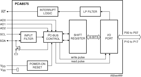
The PCA8575 provides general purpose remote I/O expansion for many microcontroller families via the two-line bidirectional I²C-Bus (serial clock (SCL), serial data (SDA)).
The device consists of a 16-bit quasi-bidirectional port and an I²C-bus interface. The PCA8575 has a low current consumption and includes latched outputs with high current drive capability for directly driving LEDs.
The PCA8575 also possesses an interrupt line (INT) which can be connected to the interrupt logic of the microcontroller. By sending an interrupt signal on this line, the remote I/O can inform the microcontroller if there is incoming data on its ports without having to communicate via the I²C-bus. The internal Power-On Reset (POR) initializes the I/Os as inputs.
図を選択する。:
|
|
|
|
|
|
|
|---|---|---|---|---|---|
|
|
|
|
|
|
|
|
|
|
|
|
|
|
|
|
|
|
|
|
|
|
|
|
|
|
|
|
|
|
|
|
|
|
|
|
|
|
|
|
|
|
|
|
|
|
|
|
|
|
|
|
|
|
|
|
|
|
|
|
|
|
|
|
|
|
|
|
|
|
クイック・リファレンス ドキュメンテーションの種類
1-10 件/全 16 ドキュメント
コンパクトリスト
NXPから直接サポートを受けるには、以下のサイトをご覧ください。 エンジニアリング・サービス.
1 エンジニアリング・サービス

この製品をサポートするその他のパートナー製品を見つけるには、当社の Web サイトにアクセスしてください パートナーマーケットプレイス.