
アプリケーション・ノート (4)
サポート情報 (2)
-
Reflow Soldering Profile[REFLOW_SOLDERING_PROFILE]
-
Footprint for wave soldering[SSOP-TSSOP-VSO-WAVE]
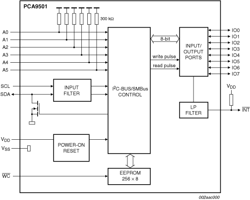
The PCA9501 is an 8-bit I/O expander with an on-board 2-kbit EEPROM.
The I/O expandable eight quasi-bidirectional data pins can be independently assigned as inputs or outputs to monitor board level status or activate indicator devices such as LEDs. The system leader writes to the I/O configuration bits in the same way as for the PCF8574. The data for each input or output is kept in the corresponding input or output register. The system leader can read all registers.
The EEPROM can be used to store error codes or board manufacturing data for read-back by application software for diagnostic purposes and are included in the I/O expander package.
The PCA9501 active LOW open-drain interrupt output is activated when any input state differs from its corresponding input port register state. It is used to indicate to the system leader that an input state has changed and the device needs to be interrogated.
The PCA9501 has six address pins with internal pull-up resistors allowing up to 64 devices to share the common two-wire I²C-bus software protocol serial data bus. The fixed GPIO address starts with '0' and the fixed EEPROM I²C-bus address starts with '1', so the PCA9501 appears as two separate devices to the bus leader.
The PCA9501 supports hot insertion to facilitate usage in removable cards on backplane systems.
|
|
|
|
|
|
|
|---|---|---|---|---|---|
|
|
|
|
|
|
|
|
|
|
|
|
|
|
|
|
|
|
|
|
|
|
|
|
|
|
|
|
|
|
|
|
|
|
|
|
|
|
|
|
|
|
|
|
|
|
|
|
|
|
|
|
|
|
|
|
|
|
|
|
|
|
|
|
|
|
|
|
|
|
クイック・リファレンス ドキュメンテーションの種類
1-10 件/全 15 ドキュメント
コンパクトリスト
2 設計・ファイル
完全な内訳を受け取ります。 製品の設置面積などについては、 eCad ファイル.
NXPから直接サポートを受けるには、以下のサイトをご覧ください。 エンジニアリング・サービス.
1 エンジニアリング・サービス

この製品をサポートするその他のパートナー製品を見つけるには、当社の Web サイトにアクセスしてください パートナーマーケットプレイス.