Getting Started with the PF8101/PF8201 Evaluation Boards
このドキュメントの内容
-
Get Started
-
Know the Board
-
Configure Hardware
-
Install Software
サインイン 進行状況を保存するには アカウントをお持ちでない方 アカウントを作成する。
お客様の PF8101/PF8201 Evaluation Boards
Get Started
The NXP analog product development boards provide an easy-to-use platform for evaluating NXP products. The boards support a range of analog, mixed-signal, and power solutions. They incorporate monolithic integrated circuits and system-in-package devices that use proven high-volume technology. NXP products offer longer battery life, a smaller form factor, reduced component counts, lower cost, and improved performance in powering state-of-the-art systems.
This page will guide you through learning about how to set up the KITPF8101FRDMEVM or the KITPF8201FRDMEVM boards.
1.1 Kit Contents/Packing List
Working with the KITPF8101FRDMEVM or the KITPF8201FRDMEVM requires the kit contents, additional hardware and a Windows PC workstation with installed software.
1.2 Kit Contents
- Assembled and tested evaluation board and preprogrammed FRDM-KL25Z microcontroller board in an anti-static bag
- 3.0ft. USB-STD A to USB-B-mini cable
- Quick Start Guide
1.3 Additional Hardware
In addition to the kit contents, the following hardware is necessary or beneficial when working with this kit.
- Power supply with a range of 3.0 V to 5.0 V and a current limit set initially to 1.0 A (maximum current consumption can be up to 7.0 A)
1.4 Windows PC Workstation
This evaluation board requires a Windows PC workstation. Meeting these minimum specifications should produce great results when working with this evaluation board.
- USB-enabled computer with Windows 7, Windows 8, or Windows 10
1.5 Software
Installing software is necessary to work with this evaluation board. Software package NXP_FlexGUI_PF8x_Rev_0.7.x or higher contains:
- KL25Z firmware files
- NXP PF8x FlexGUI
1.6 User Manual
Refer to UM11213 - PF8101_PF8201 Evaluation Boards - User Guide [English] for full evaluation board functionality.
Know the Board
2.1 Board Overview
The KITPF8101FRDMEVM or the KITPF8201FRDMEVM provide an easy-to-use platform for evaluating NXP products. The boards support a range of analog, mixed-signal and power solutions. They incorporate monolithic integrated circuits and system-in-package devices that use proven high-volume technology. NXP products offer longer battery life, a smaller form factor, reduced component counts, lower cost and improved performance in powering state-of-the-art systems.
These customer evaluation boards feature the PF8101/PF8201 power management IC. The kits integrates all hardware needed to fully evaluate the PMIC. They integrate a communication bridge based on the FRDM-KL25Z freedom board to interface with the FlexGUI software interface to fully configure and control the PF8101/PF8201 PMIC.
2.2 KITPF8101FRDMEVM / KITPF8201FRDMEVM Evaluation Boards Features
Buck regulators
- SW1, SW2, SW5, SW6: 0.4 V to 1.8 V; 2500 mA; 2 % accuracy and dynamic voltage scaling and single, dual, triple or quad-phase configuration
- SW7; 1.0 V to 4.1 V; 2500 mA; 2 % accuracy
- Configurable VTT termination mode on SW6
- Programmable current limit
- Spread-spectrum and manual tuning of switching frequency
LDO regulators
- 3x LDO regulator 1.5 V to 5.0 V, 400 mA: 3 % accuracy with optional load switch mode
- Selectable hardware/software control on LDO2
RTC supply VSNVS 1.8 V/3.0 V/3.3 V, 10 mA
- Battery backed memory including coin cell charger with programmable charge current and voltage
System features
- 2.5 to 5.5 V operating input voltage range
- USB to I²C communication via the FRDM-KL25Z interface
- Selectable hardwire default PMIC configuration or OTP/TBB operation
- Fast mode I²C communication at 400 kHz (high-speed operation supported by PMIC)
- Advance system monitoring/diagnostic via PMIC and/or system AMUX
- Controller/target interface connector
- Onboard I/O regulator with 1.8 V/3.3 V selectable output voltage
Attached FRDM_KL25Z
- Pre-programmed FRDM-KL25Z as a communication link between the EVB and a PC
- The Freedom KL25Z is an ultra-low-cost development platform for Kinetis® L Series KL1x (KL14/15) and KL2x (KL24/25) MCUs built on Arm® Cortex®-M0+ processor.
- Features include easy access to MCU I/O, battery-ready, low-power operation, a standards-based form factor with expansion board options and a built-in debug interface for flash programming and run-control.
2.3 Product Descriptions
The KITPF8101FRDMEVM / KITPF8201FRDMEVM are a hardware evaluation boards that allow the full evaluation of the PF8101/PF8201. The PF8101/PF8201 family of devices feature power management integrated circuit (PMIC) designed for high performance i.MX 8 and S32V based applications. It features seven high efficiency buck converters and four linear regulators for powering the processor, memory and miscellaneous peripherals.
Built-in one time programmable memory stores key startup configurations, drastically reducing external components typically used to set output voltage and sequence of external regulators. Regulator parameters are adjustable through high-speed I²C after start up offering flexibility for different system states.
The PF8101/PF8201 family comprises two versions of this PMIC, to address different market needs:
- PF8201 is the flagship version of this family providing a full feature PMIC with integrated functional safety mechanism to comply with the ISO 26262 standard and providing a powerful and flexible solution for ASIL B(D) automotive modules.
- PF8101 is the non-safety version of this product, providing all the power management and digital control included in PF8201, without the functional safety overhead to provide a more economic platform for non-safety systems.
| Device | Description | Features |
|---|---|---|
| PF8101 | 9- Channel Power Management Integrated Circuit (PMIC) for high-performance processing applications |
|
| PF8201 | 9- Channel Power Management Integrated Circuit (PMIC) for high-performance processing applications |
|
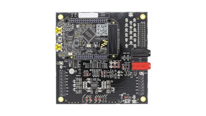
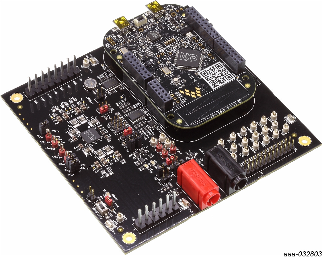
2.4 Board Image
The KITPF8101FRDMEVM / KITPF8201FRDMEVM consists of a multiple boards with FRDM-LKL25 as shown in the final assembly below.
2.5 Additional Board Support
Board overview/ components, jumper configurations, test points, connectors and additional board descriptions / images are available in the User Guide. Refer to UM11213 - PF8101_PF8201 Evaluation Boards - User Guide [English]
Configure Hardware
3.1 Configuration the Hardware
This section summarizes the overall setup. Detail description is provided in the user guide.
Suggested equipment’s needed for test:
- 3.0 V to 5.0 V power supply (using banana jacks)
- Computer
- Mini USB type A Cable

3.3 Device Considerations
It is recommended to learn about the device and its specifications prior to operating the boards. The device has a high level of flexibility due to parameter configuration available in the OTP. This impacts the functionality of the device. It is key to understand how the parameters are programmed on the device.
3.4 Setting Up the Board
To configure the hardware and workstation as illustrated.
- With the USB cable connected to the PC and the USB port in the freedom board, apply VIN to the
evaluation board.
- Provide external VIN between 2.5 to 5.5 V on J10 (VIN) and J4 (GND)
- Short jumper J17 to provide 3V3 Vin from Freedom board (use this mode of operation for functional demonstration only, no regulation loading allowed in this mode)
- Press Reset on the Freedom board, to ensure that board is properly recognized.
- Browse to the NXP_FlexGUI/bin/ folder and double-click on the flexgui-app-8xxx.jar executable to start the application.
- The FlexGUI launcher is displayed with a list of possible configurations to load the FlexGUI. Select the appropriate option for device and silicon revision to be used. If the device revision populated on the evaluation board is not available in the list, please contact your NXP representative to obtain the latest software update suitable for your device.
3.5 Additional Board Support
Detailed configuration, Flex GUI options are detailed in the User Guide. Refer UM11213 - PF8101_PF8201 Evaluation Boards - User Guide [English]
Install Software
4.1 Preparing Graphical User Interface Operating Environment
Download and run SW for the KITPF8101FRDMEVM or the KITPF8201FRDMEVM. These evaluation boards use FlexGUI software for PF8101/PF8201 device. Prior to the installation of the FlexGUI software and performing device firmware updates (if needed), download and unzip the NXP_FlexGUI_PF8x_REV_0.7.x.zip file to any desired location.
4.2 Installing the Java JRE
- Download Java JRE (Java SE Runtime Environment), available at http://www.oracle.com/technetwork/java/javase/downloads/jre8-downloads-2133155.html (8u162 or newer)
- Open the installer and follow the installation instructions
- Following the successful installation, restart the computer
4.3 Installing FlexGUI Software Package
The FlexGUI software installation requires only extracting the zip file in a desired location.
- If necessary, install the Java JRE and Windows 7 FlexGUI driver.
- Download the latest FlexGUI (32-bit or 64-bit) version,
NXP_FlexGUI_PF8x_REV_0.7.x.zip. - Extract all the files to a desired location on your PC. FlexGUI is started by running the batch
file,
NXP_FlexGUI_PF8x_Rev_0.7.x\NXP FlexGUI\bin\flexgui-app-pf8xxxx.bat.
The FlexGUI Rev 0.7.0 or higher, interfaces with the FRDM-KL25Z freedom board via USB-HID protocol which should be recognized automatically by the Windows OS eliminating the need for any extra hardware drivers. Refer to UM11213 Section 5.4 "Updating the PF8101/PF8201 FlexGUI firmware" for details on how to update the FRDM-KL25Z, in case the board is not loaded with the latest firmware with USB-HID support.
4.4 Updating the PF8101/PF8201 FlexGUI Firmware
The FRDM-KL25Z freedom board is used as a communication bridge to interface the FlexGUI with the PMIC and other I²C devices. The firmware is organized in three levels:
- At first level, the SDA uses the BOOTLOADER to operate as the main path to flash the functional code of the SDA processor. The BOOTLOADER is preprogrammed on the FRDM-KL25Z freedom boards and cannot be reflashed to avoid permanent damage to the Freedom board.
- At second level, the SDA provides a firmware loader for drag and drop update of the KL25Z MCU firmware.
- At the third level, the KL25Z MCU provides the FlexGUI firmware in charge of converting the USB communication into MCU instructions to control digital I/Os as well as I²C communication to the PMIC. If the FRDM-KL25Z is not loaded with the correct firmware to support a future software upgrade, the firmware can be updated in few simple steps.
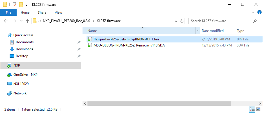
4.5 Flashing the FRDM-KL25Z Firmware Loader
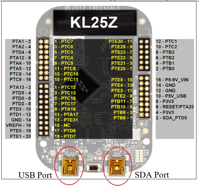
- Press the push button on the Freedom board and connect the USB cable into the SDA port on the Freedom board. A new BOOTLOADER device should appear on the left pane of the file explorer.
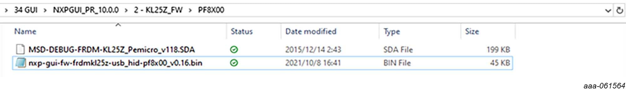
- Drag and drop the file MSD-DEBUG-FRDM-KL25Z_Pemicro_v118.SDA into the BOOTLOADER drive. File should be located in the KL25Z firmware folder.
- Disconnect and reconnect the USB cable into the SDA port (this time without pressing the push button). A new device called FRDM_KL25Z is installed on the PC.
4.6 Flashing the FlexGUI Firmware
If a new software or silicon release requires a firmware update on the FRDM-KL25Z freedom board, use the following procedure to upgrade or downgrade the firmware of the freedom board as needed. Note that this procedure is needed only to update the firmware and may be skipped if no change is needed.
- Connect the USB cable in the SDA port (without holding the push button).
- Locate the ".bin" FlexGUI driver to be installed, for example
flexgui-fw-kl25z-usb-hidpf8x00-
                v0.1.1.bin
, drag and drop the file into the FRDM_KL25Z driver. - Freedom board firmware is successfully loaded.
4.7 Complete Step by Step
Complete step by step software instructions are detailed in the User Guide. Refer to UM11213 - PF8101_PF8201 Evaluation Boards - User Guide [English]
Design Resources
Learn More
Success
Now start embedded application development
Product Summary Page
Tool Summary Page
'The overview section' provides an overview of the device, product features, a description of the kit contents, a list of (and links to) supported devices, list of (and links to) any related products and a 'Get Started' section.
- 'Documentation': download current documentation
- 'Software and Tools': download current hardware and software tools / Drivers
- 'Buy/Parametrics': purchase the product and view the product parametrics.
- 'Build a package': the bill of materials (BOM) and supporting schematics are also available for download in the 'Get Started' section.
After downloading files, review each file, including the user guide which includes setup instructions.
For the Entire Solution
In addition to our PF8101_PF8201: 9-CHANNEL Power Management Integrated Circuit (PMIC) for high-performance processing applications page you may also want to visit:
Product pages: i.MX8X:i.MX 8X Family - Arm® Cortex®-A35, 3D Graphics, 4K Video, DSP, Error Correcting Code on DDR
Hardware pages: Analog Toolbox
Software pages: Analog Expert Software and Tools
Community page: Power Management
Chip Documents
Board Information
このページ
- 1.1
Kit Contents/Packing List
- 1.2
Kit Contents
- 1.3
Additional Hardware
- 1.4
Windows PC Workstation
- 1.5
Software
- 1.6
User Manual
- 2.1
Board Overview
- 2.2
KITPF8101FRDMEVM / KITPF8201FRDMEVM Evaluation Boards Features
- 2.3
Product Descriptions
- 2.4
Board Image
- 2.5
Additional Board Support
- 3.1
Configuration the Hardware
- 3.2
Configuration Image
- 3.3
Device Considerations
- 3.4
Setting Up the Board
- 3.5
Additional Board Support