- アナログ・ツールボックス
- PCT2075DP-ARD評価ボードのスタート・ガイド
PCT2075DP-ARD評価ボードのスタート・ガイド
サインイン 進行状況を保存するには アカウントをお持ちでない方 アカウントを作成する。
お客様の PCT2075DP-ARD Arduino®シールド - 温度センサ
1. はじめに
NXPのアナログ製品開発ボードは、NXP製品の評価を目的とした使いやすいプラットフォームです。さまざまなアナログ・ソリューション、ミックスド・シグナル・ソリューション、パワー・ソリューションに対応しています。実績のある大容量テクノロジを使用したモノリシック集積回路およびシステム・イン・パッケージ (SiP) デバイスを搭載しています。NXP製品は、最先端システムへの電源供給において、より長いバッテリー寿命、より小さいフォーム・ファクタ、より少ない部品数、より低いコスト、改善されたパフォーマンスを実現します。
このページでは、PCT2075DP-ARD評価ボードをセットアップして使用する手順について説明します。
1.1 キットの内容/同梱物一覧
PCT2075DP-ARDには以下のものが含まれています。
- 組立て済み/テスト済みの評価ボード(静電気防止バッグ入り)
- クイック・スタート・ガイド
1.2 前提条件
I²Cバスの知識があると役立ちますが、必須ではありません。
1.3 静電気処理要件
このデバイスは静電気放電 (ESD) に敏感です。したがって、輸送および取り扱いの際には注意が必要です。ハードウェアの開梱または取り扱い前には、グランド・ストラップを使用するか、PCケースまたはその他の接地された箇所に触れてください。
1.4 最小システム要件
この評価ボードにはWindows PCワークステーションが必要です。この評価ボードで作業する際は、これらの最低限の仕様を満たすことで良好な結果が得られます。
- Windows 10を搭載したコンピュータ
- 1つのUSBポート(3.0、2.0、または1.1互換)
- 3つのEVKボード(MIMXRT1050-EVK、LPC55S69-EVK、8MMINILPD4-EVK)のいずれか1つと、関連するファームウェア/GUIソフトウェア
- PCとEVKボード間の電源およびデータ接続用USBケーブル(EVKのパッケージに含まれていない場合)
2. ハードウェアについて
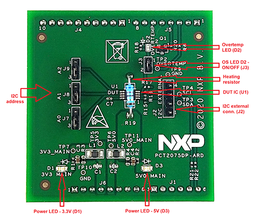
2.1 ボードの特長
- I²Cバスへの外部アクセス用コネクタ
- オン/オフ制御回路付きオンボード発熱抵抗体
- 過熱シグナル用オンボードLED
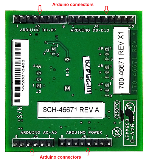
- Arduinoデバイスと直接接続するためのArduino Uno R3ポートを搭載
- MIMXRT1050-EVKボードとの完全な互換性、GUIを含む (Windows 10)
- LPC55S69-EVKボードとの完全な互換性、GUIを含む (Windows 10)
- 8MMINILPD4-EVKボードとの互換性、GUIを含む (Windows 10)
2.2 ボードの説明
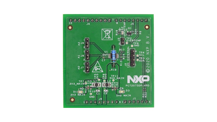
この評価ボードはPCT2075DP ICをベースに構築され、Arduinoポート経由でさまざまなArduino互換(オリジナルのArduino Uno R3を含む)ボードに接続できる拡張ボードとして機能します。このボードは、NXP Semiconductorsによって製造されたPCT2075DP 1°C精度デジタル温度センサおよび温度ウォッチドッグの特性をテストおよび測定することを目的としています。
さらに、この拡張ボードは、NXPの各評価ボード(MIMXRT1050-EVKボード、LPC55S69-EVK開発ボード、8MMINILPD4-EVKボード)向けのソフトウェア・サポートとグラフィカル・ユーザー・インターフェース(Windowsプラットフォーム)も備えています。
3. ソフトウェアのインストール
3.1 ソフトウェアのインストール
PCT2075DP-ARD評価ボードは、Arduinoポートを搭載したマザーボードとともに動作する拡張ボードとして設計、構築されています。このボードは、以下のNXP評価ボードと完全に互換性を持つように設計されています。
各EVKボードに必要なファームウェアは、NXPからダウンロードできます。EVKとPCT2075DP-ARDのペアを起動する前に、対応するファームウェア・パッケージを使用してEVKマザーボードをプログラミングする必要があります。さらに、同じNXPのサイトからGUIアプリケーション (Windows 10) をダウンロードでき、いずれかのEVKを使用してPCT2075DP-ARD拡張ボードの迅速なテストと操作が可能になります。GUIアプリケーションは、3つのEVKすべてに共通です。
ソフトウェアをインストールしたら、最初のステップとして、GUIからEVK/拡張ボードの正しい組み合わせを選択します。それにより、ボードをGUIインターフェースから制御できるようになります。
4. ハードウェアの構成
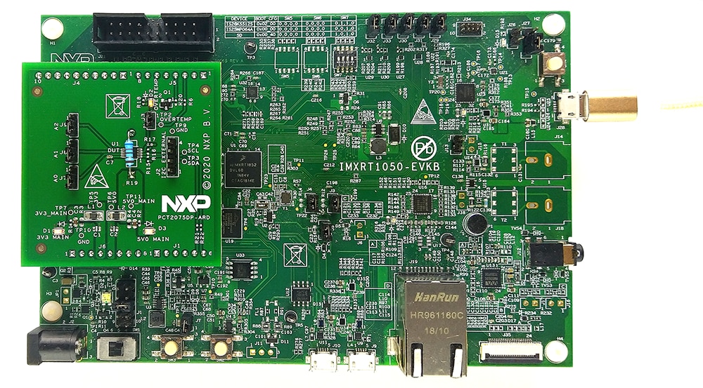
4.1 PCT2075DP-ARDをMIMXRT1050-EVKボードとともに使用
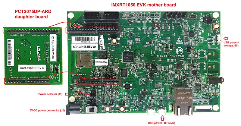
図1は、MIMXRT1050-EVKを使用したPCT2075DP-ARD拡張ボードの動作に必要なハードウェアを示しています。
- MIMXRT1050-EVKボード x 1
- PCT2075DP-ARD拡張ボード x 1
- USB-A/USB Micro-Bケーブル x 1
- Windows 10オペレーティング・システムを搭載したPC
MIMXRT1050-EVKボードには、次の3つの異なるコネクタから給電できます。
J2バレル電源コネクタに外部の5.0 V DC電源を接続するJ9USB Micro-Bコネクタ (J9) を介してUSBポートから直接給電するJ28コネクタを介して同じUSBポートから給電する
J28はデバッグ・コネクタとして使用できるため、同じUSBケーブルを通してJ28を使用することで、EVKへの給電と同時に、PCとリンクさせてデータ交換を行うことができます。
(PC上の)古いUSBポートからは、必要な電流 (500 mA) を供給することができません。通信を確立する前に、外部電源(J2に接続)を使用してください。J1(図1を参照)を使用して、マザーボードの電源構成を選択できます。詳細については、i.MX RT1050評価キットを参照してください。
ハードウェアとワークステーションを構成するには、以下の手順を実施します。
- EVKの適切な電源構成を設定します (
J1)。電源にJ28を使用する場合は、J1ジャンパを5-6の位置に配置する必要があります。外部電源(J2に接続)を使用する場合は、ジャンパJ1を1-2の位置に配置します - EVKのArduinoポートにPCT2075DP-ARD拡張カードを挿入します(図1を参照)
J28コネクタを使用してMIMXRT1050-EVKボードをコンピュータのUSBポートに接続します- IMXRT1050のターゲット・ファームウェアをインストールします(NXPからダウンロードし、UM11581:ArduinoシールドのGUIとファームウェアのインストール・ユーザー・ガイドに記載された手順を参照)
- GUIアプリケーションをPCにインストールします(UM11581:ArduinoシールドのGUIとファームウェアのインストール・ユーザー・ガイドを参照)。
- GUIアプリケーションを開き、PCからデバイスを操作します
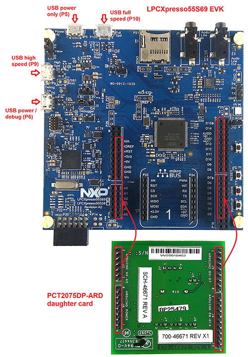
4.2 PCT2075DP-ARDをLPC55S69-EVKボードとともに使用
図3は、PCT2075DP-ARDおよびLPC55S69-EVKボードの動作に必要なハードウェアを示しています。
- LPC55S69-EVKボード x 1
- PCT2075DP-ARD拡張ボード x 1
- USB-A/USB Micro-Bケーブル x 1
- Windows 10オペレーティング・システムを搭載したPC
LPC55S69-EVKボードには、4つのUSB Micro-BコネクタP5、P6、P9、P10が搭載されています。ボードには任意のUSBポートから電源を供給できます。P6 USBコネクタを使用してボードをPCに接続すると、P6がデバッグ用に指定され、USBケーブルによってボードへの電源供給と同時にEVKボードとPC間のデータ・リンクが確立されるため、起動操作が簡単になります。詳細については、LPCXpresso55S69開発ボードを参照してください。
ハードウェアとワークステーションを構成するには、以下の手順を実施します。
- PCT2075DP-ARD拡張カードをLPC55S69-EVK開発ボード上の
P16–P19コネクタに差し込みます(図3でマークされたP16–P19のピンを参照) - ポート
P6を使用して、開発ボードをPCのUSBポートに接続します - LPCXpresso55S69のターゲット・ファームウェアをインストールします(NXPからダウンロードし、UM11581に記載された手順を参照)
- GUIアプリケーションをPCにインストールします(UM11581:ArduinoシールドのGUIとファームウェアのインストール・ユーザー・ガイドを参照)。
- GUIアプリケーションを開き、PCからデバイスを操作します
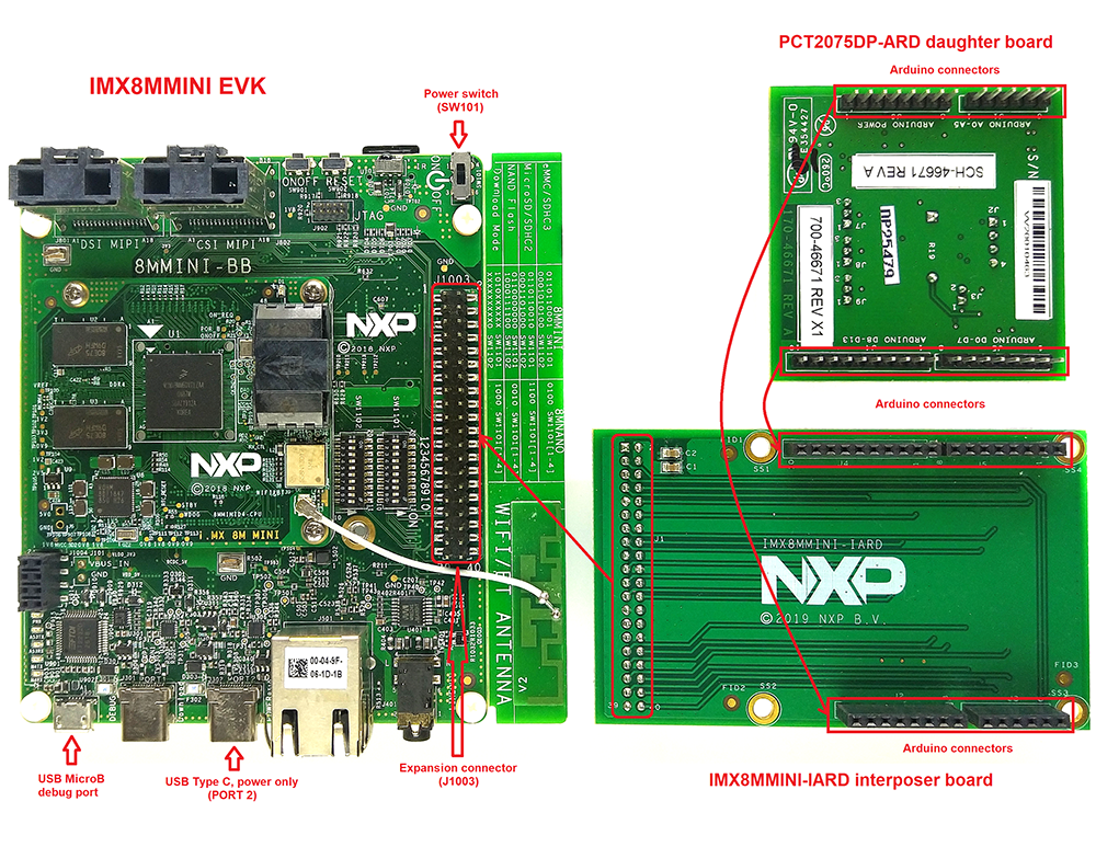
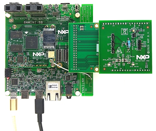
4.3 PCT2075DP-ARDを8MMINILPD4-EVKボードとともに使用
PCT2075DP-ARDの動作用に8MMINILPD4-EVKボードを使用する場合、EVKと拡張ボード間の相互接続として特別に設計および構築されている3番目のボード(IMX8MMINI-IARDインターポーザ・ボード)を使用する必要があります。8MMINILPD4-EVKにはArduinoポートが搭載されていません。代わりに、2 x 20ピン拡張コネクタJ1003(8MMINILPD4-EVKユーザー・マニュアル参照)が搭載されています。J1003は、専用のI²CバスやSPIバスなどのさまざまなデジタルI/Oラインを備えた多目的ポートです。拡張コネクタのピン・チャートを元に、Arduinoポート・インターポーザ・ボードが開発されました。
図5に示すセットアップ・アセンブリには、EVKと拡張ボードに加えて3番目のボードが含まれています。このセットアップに給電し、操作するには、給電用のUSB-Cケーブル(図6を参照)をEVKボードのポート2に接続する必要があります。ボードには電源スイッチ (SW101) が搭載されており、電源を入れるにはこれをONポジションにします。PCとEVKのデバッグ・ポート (J901) に接続されたもう1本の (USB Micro-B) ケーブルを介して、データ通信が確立されます。
拡張ボードをEVKに取り付けるには、IMX8MMINI-IARDインターポーザ・ボードを使用する必要があります。PCT2075DP-ARDをインターポーザのArduinoコネクタに接続してから、インターポーザをi.MX 8M Mini EVKボード上の拡張コネクタ (J1003) に接続します(図5を参照)。8MMINILPD4-EVKユーザー・マニュアルおよびIMX8MMINI-IARDユーザー・マニュアルに、セットアップ・アセンブリの電源投入と操作に関する詳細が記載されています。
ハードウェアとワークステーションを構成するには、以下の手順を実施します。
- PCT2075DP-ARDをIMX8MMINI-IARDインターポーザ・ボードの上面にあるArduinoコネクタに挿入します
- 組み合わされたボードをEVKに取り付けます(IMX8MMINI-IARDの裏面にある
J1コネクタを、8MMINILPD4-EVKボードの上面にあるJ1003拡張コネクタに接続します) - ポート2に接続したUSB Type-Cケーブルを使用して、EVKボードの電源を入れます
J901デバッグ・ポートに接続したUSB Micro-Bケーブルを使用して、EVKをPCに接続しますSW101をONポジションにしてボードの電源を投入します- MIMXRT1050のターゲット・ファームウェアをインストールします(NXPからダウンロードし、UM11581:ArduinoシールドのGUIとファームウェアのインストール・ユーザー・ガイドに記載された手順を参照)
- GUIアプリケーションをPCにインストールします
- GUIアプリケーションを開き、PCからデバイスを操作します
4.4 PCT2075DP-ARDを他のArduinoデバイスとともに使用
PCT2075DP-ARD拡張ボードは、Arduinoポートを備えた他のEVKボードと組み合わせても動作できます。ボードの接続方法としては、Arduinoポートを搭載した他のEVKを使用する方法と、Arduinoポートを搭載していないEVKを使用する方法の2つがあります。
1つ目の方法の場合は、PCT2075の仕様に従ってファームウェアを作成してから、EVKにPCT2075DP-ARD拡張ボードを取り付けてボードを操作します。
2つ目の方法では、Arduinoコネクタのピン・チャートを使用して、必要な電気的接続(電源、I²Cバス、および制御ライン)を行い、ICの仕様に準拠して必要なファームウェアを作成します。PCT2075データ・シートを参照し、PCT2075の内部レジスタの詳細、および内部コントローラとEVK間のデータ交換の詳細を確認してください。ICの損傷を防止するために、必ず電気的接続を正しく行い、信号線でのデータ競合を回避します。
設計・リソース
ボードに関するドキュメント
サポート
フォーラム
NXPのいずれかのコミュニティ・サイトで、他のエンジニアとつながり、PCT2075DP-ARDを使用した設計に関する専門的なアドバイスを受けることができます。