アプリケーション・ノート (1)
カタログ (1)
データ・シート (1)
-
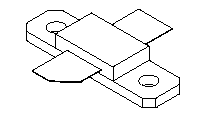
MRFE6VS25L 1.8-2000 MHz, 25 W, 50 V Data Sheet[MRFE6VS25L]
Contact support, your local sales representative or an NXP Authorized Distributor for product availability.
| Frequency (MHz) |
Signal Type | Pout (W) |
Gps (dB) |
ηD (%) |
IMD (dBc) |
| 1.8 to 30(1,3) | Two-Tone (10 kHz spacing) | 25 PEP | 25.0 | 50.0 | –28 |
| Frequency (MHz) |
Signal Type | Pout (W) |
Gps (dB) |
ηD (%) |
IMD (dBc) |
| 30-512(2,3) | Two-Tone (200 kHz spacing) | 25 PEP | 17.3 | 32.0 | –32 |
| Frequency (MHz) |
Signal Type | Pout (W) |
Gps (dB) |
ηD (%) |
| 512(4) | Pulse (100 µsec, 20% Duty Cycle) | 25 Peak | 25.9 | 74.0 |
| 512(4) | CW | 25 | 26.0 | 75.0 |
| Frequency (MHz) |
Signal Type | VSWR | Pin (W) |
Test Voltage |
Result |
| 30(1) | CW | >65:1 at all Phase Angles | 0.11 (3 dB Overdrive) | 50 | No Device Degradation |
| 512(2) | CW | 0.95 (3 dB Overdrive) | |||
| 512(4) | Pulse (100 µsec, 20% Duty Cycle) | 0.14 Peak (3 dB Overdrive) | |||
| 512(4) | CW | 0.14 (3 dB Overdrive) |
|
|
|
|
|
|
|
|---|---|---|---|---|---|
|
|
|
|
|
|
|
|
|
|
|
|
|
|
|
|
|
|
|
|
|
|
|
|
|
|
|
|
|
|
|
|
|
|
|
|
|
|
|
|
|
|
|
|
|
|
|
|
|
|
|
|
|
|
|
|
|
|
|
|
|
|
|
|
|
|
|
|
|
|
クイック・リファレンス ドキュメンテーションの種類
4 ドキュメント
コンパクトリスト
1-5件/全 11 設計・ファイル
完全な内訳を受け取ります。 製品の設置面積などについては、 eCad ファイル.