MIMXRT1040-EVKのスタート・ガイド
このドキュメントの内容
-
接続
-
ソフトウェアの入手
-
ビルドと実行
サインイン 進行状況を保存するには アカウントをお持ちでない方 アカウントを作成する。
お客様の i.MX RT1040-EVK
1. 接続
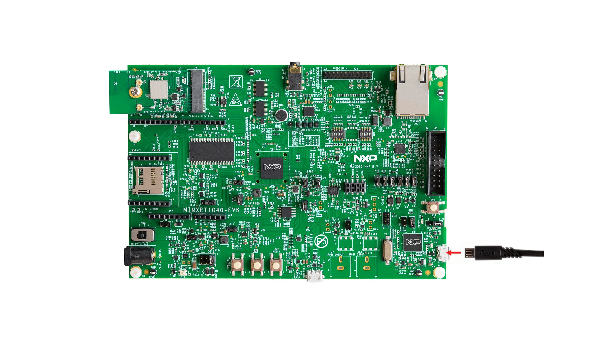
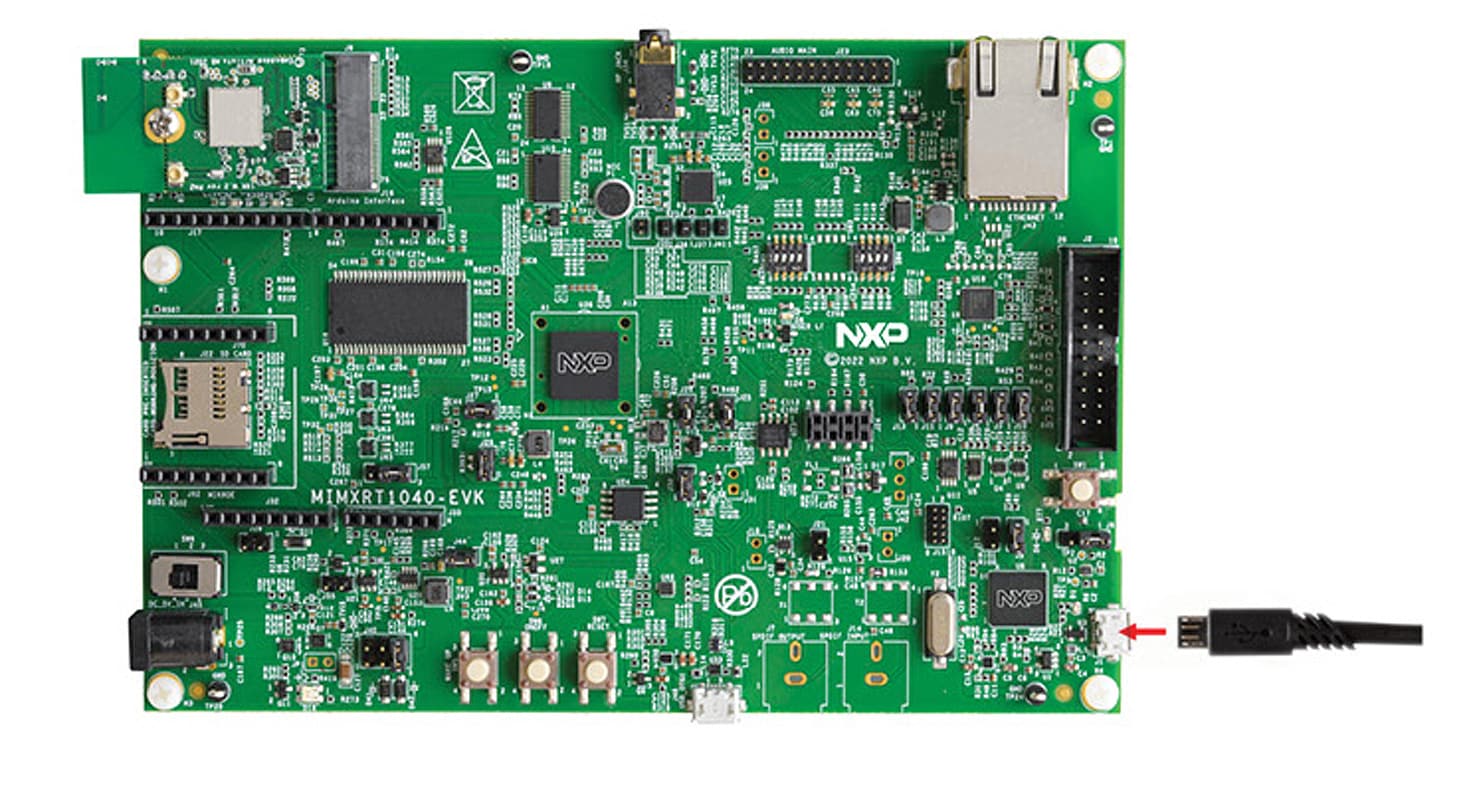
MIMXRT1040-EVKを実際に使ってみましょう。下の図はMIMXRT1040-EVKの画像を示しています。

1.1 ブート・モードの設定
デバイスには4つのブート・モードがあります(1つはNXP用に予約済みです)。ブート・モードは、内部BOOT_MODEレジスタに格納されているバイナリ値に基づいて選択されます。MIMXRT1040-EVKボードのブート・モードの選択にはスイッチSW4が使用されます。
QSPIフラッシュからブートするには、SW4が0010に設定されていることを確認してください。
1.2 USBケーブルを接続する
MIMXRT1040-EVKには、接続されるとボード上のLEDが定期的に点滅するデモが事前にプログラム済みです。ボードを傾けると、緑色LEDがX軸上の傾きの度合いに基づいて徐々に点灯します。
2. ソフトウェアの入手
2.1 MCUXpresso SDKですぐに設計を開始する
MCUXpresso SDKは無償で利用することができ、オープンソースのライセンスに基づいて、すべてのハードウェア抽象化およびペリフェラル・ドライバ・ソフトウェアのソース・コード全体が提供されます。
下のボタンをクリックして、MIMXRT1040-EVK用に事前設定済みのSDKリリースをダウンロードしてください

オンラインのSDK Builderにアクセスし、提供されているSDKビルダを使用してMIMXRT1040-EVK用のカスタムSDKパッケージを作成することもできます。
2.2 ツールチェーンをインストールする
NXPは、MCUXpresso IDEというツールチェーンを無償で提供しています。
別のツールチェーンを使用したい場合は?
問題ありません。MCUXpresso SDKは、IAR、Keil、コマンドラインGCCなどの他のツールをサポートしています。

2.3 PCを設定する
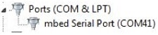
サンプル・アプリケーションの多くは、マイクロコントローラのUARTを介してデータを出力します。ボードの仮想COMポート用ドライバがインストールされているか必ず確認してください。ドライバのインストーラを実行する前に、ボードをPCに接続しておく必要があります。
シリアル・ポート・ドライバをインストールした状態で、お好きなターミナル・アプリケーションを実行し、マイクロコントローラのUARTからのシリアル出力を確認します。ターミナルをボーレート115200、8データ・ビット、パリティなし、1ストップ・ビットに設定します。MIMXRT1040-EVKの仮想COMポートのポート番号を確認するには、デバイス・マネージャを開き、「Ports(ポート)」グループでポートを探します。
ターミナル・アプリケーションの使用方法がわからない場合は、次のいずれかのチュートリアルをお試しください。
Tera Termチュートリアル、PuTTYチュートリアル3. ビルドと実行
3.1 MCUXpresso SDKサンプル・コードを確認する
MCUXpresso SDKには、サンプル・アプリケーション・コードが豊富に用意されています。利用可能なコードを確認するには、SDKをインストールしたフォルダのSDKボード・フォルダを参照し、ボード「MIMXRT1040-EVK」(
特定のサンプル・コードの詳細については、サンプルのディレクトリにあるreadme.txtファイルを開いてください。
3.2 MCUXpresso SDKサンプルのビルド、実行、およびデバッグ
興味のあるデモ・アプリケーションやドライバのサンプルがいくつかあれば、それをビルドおよびデバッグする方法を知りたくなることでしょう。MCUXpresso SDKのスタート・ガイドでは、SDKでサポートされているすべてのツールチェーンのデモを設定、ビルド、およびデバッグする方法について、わかりやすく手順に沿って解説しています。
以下のガイドを参照し、MCUXpresso IDEでサンプル・アプリケーションを開いてビルドやデバッグを行う方法を習得してください。
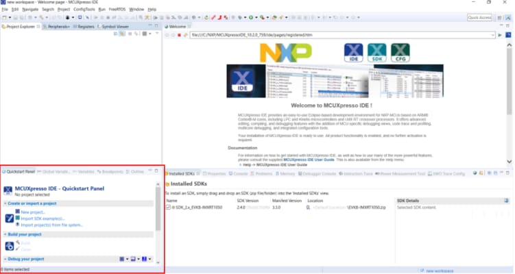
MCUXpresso IDEを使用する
MCUXpresso SDKのインポート
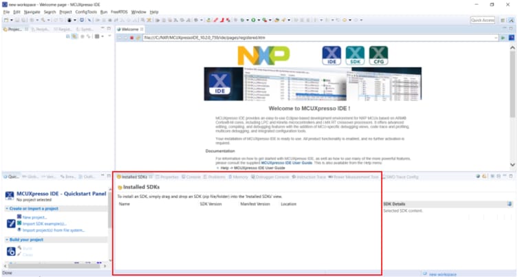
- MCUXpresso IDEを開きます
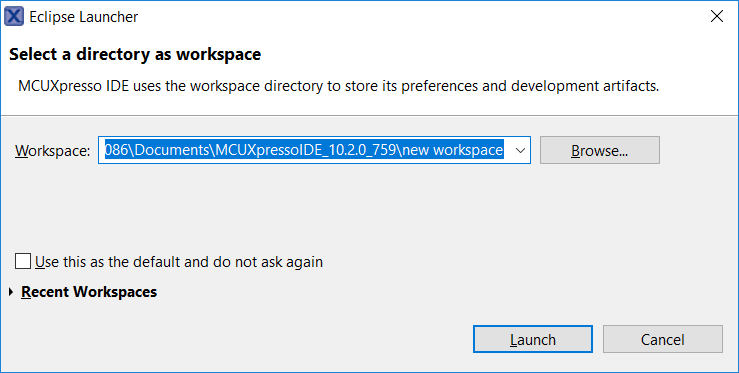
- コンピュータでワークスペースのディレクトリを選択します
- MCUXpresso IDEウィンドウ内のビューを[Installed SDKs(インストール済みSDK)]に切り替えます
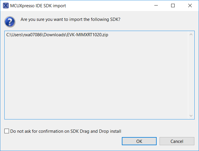
- Windowsエクスプローラを開き、EVK-MIMXRT1040 SDKのzipファイルを[Installed SDKs(インストール済みSDK)]ビューにドラッグ&ドロップします
- 次のプロンプトが表示されます。[OK]をクリックしてインポートを続行します。
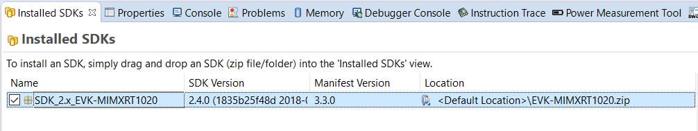
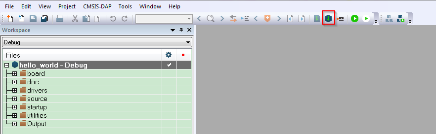
- インストールされたSDKは、以下に示すように[Installed SDKs(インストール済みSDK)]ビューに表示されます。
サンプル・アプリケーションのビルド
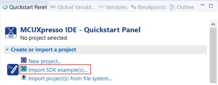
次の手順に従ってhello_worldサンプルを開きます。
-
左下隅にある「Quickstart Panel(クイックスタート・パネル)」を確認します
-
その中の[Import SDK example(s)...(SDKサンプルのインポート)]をクリックします。
-
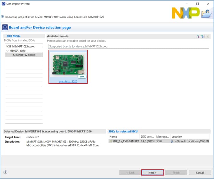
サンプルをインポートして実行させるボードとして「evkMIMXRT1040ボード」をクリックして選択し、[Next(次へ)]をクリックします
-
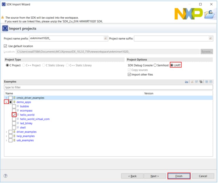
矢印ボタンを使用して[demo_apps]カテゴリを展開し、hello_worldの横にあるチェックボックスをクリックしてそのプロジェクトを選択します。[SDK Debug Console(SDKデバッグ・コンソール)]として[UART]が選択されていることを確認してください。その後、[Finish(完了)]をクリックします
-
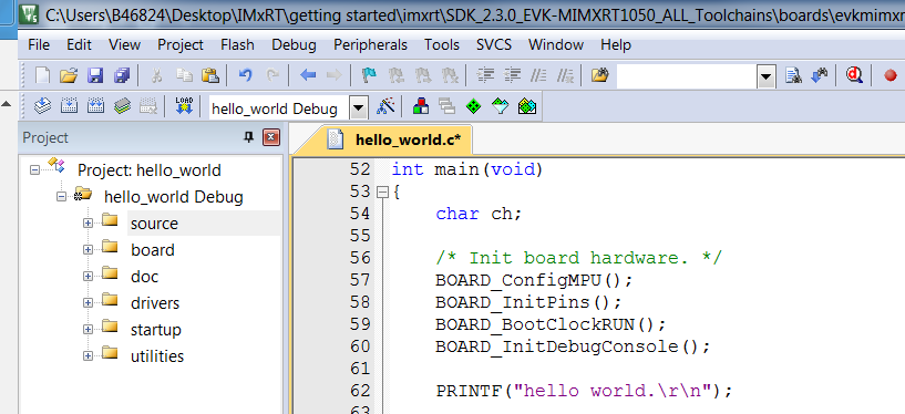
ここで、プロジェクト名をクリックし、[Build(ビルド)]アイコンをクリックして、プロジェクトをビルドします
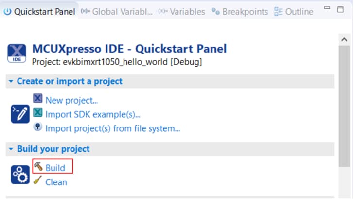
-
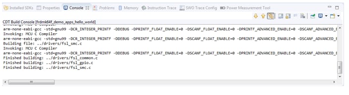
ビルドの進捗状況は[Console(コンソール)]タブで確認できます
サンプル・アプリケーションの実行
- プロジェクトがコンパイルされたので、ボードにフラッシュしてプロジェクトを実行できます
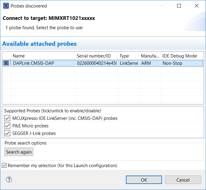
- MIMXRT1040-EVKのOpenSDAデバッグ・コネクタにUSBケーブルが接続されていることを確認し、「Quickstart Panel(クイックスタート・パネル)」の[Debug(デバッグ)]をクリックします
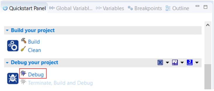
- MCUXpresso IDEは接続されたボードを検出します。MIMXRT1040-EVKに統合されたOpenSDA回路の一部であるCMSIS-DAPデバッグ・プローブが検出される必要があります。[OK]をクリックして続行します
- ファームウェアがボードにダウンロードされ、デバッガが起動します
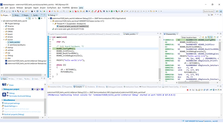
- ターミナル・プログラムを開き、ボードが列挙したCOMポートに接続します。ボーレート115200、8データ・ビット、パリティなし、1ストップ・ビットを使用します
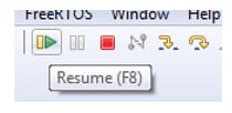
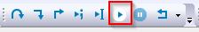
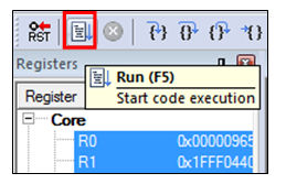
- [Resume(再開)]ボタンをクリックすると、アプリケーションが開始されます。
-
hello_worldアプリケーションが実行され、ターミナルにバナーが表示されます。表示されない場合は、ターミナルの設定と接続を確認してください
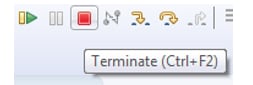
- 命令の一時停止、ステップ・イン、ステップ・オーバーを行うにはメニュー・バーのコントロールを使用します。デバッグ・セッションを停止するには、[Terminate(終了)]アイコンをクリックします。
別のツールチェーンを使用する場合:
IAR EWARMを使用する
サンプル・アプリケーションのビルド
次の手順に従ってhello_worldサンプル・アプリケーションを開きます。他のサンプル・アプリケーションでは、手順がわずかに異なる場合があります。アプリケーションによってはパスのフォルダ階層が深くなるためです。
-
目的のデモ・アプリケーション・ワークスペースをまだ開いていない場合はここで開きます。ほとんどのサンプル・アプリケーション・ワークスペースのファイルは、次のパスに置かれています。
/boards/ / / /iar hello_worldデモをサンプルとして使用する場合、パスは以下に置かれています。/boards/evkMIMXRT1040/demo_apps/hello_world/iar/hello_world.eww -
ドロップダウン・リストから、目的のビルド・ターゲットを選択します。
ここでは、「
hello_world - Debug」ターゲットを選択します。
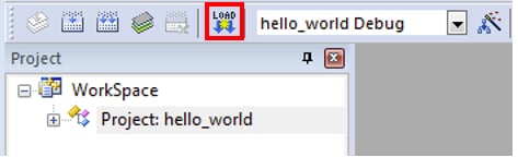
- デモ・アプリケーションをビルドするには、下の図で赤色でハイライト表示されている[Make(作成)]ボタンをクリックします
- ビルドが正常に完了します
サンプル・アプリケーションの実行
アプリケーションをダウンロードして実行するには、以下の手順に従います。
- 開発プラットフォームをUSBケーブルでPCに接続します
-
PCのターミナル・アプリケーション(PuTTY、Tera Termなど)を開き、デバッグのCOMポートに接続します。次の設定値を用いてターミナルを設定します。
- ボーレート115200(board.hファイルのBOARD_DEBUG_UART_BAUDRATE変数を参照)
- パリティなし
- 8データ・ビット
- 1ストップ・ビット
- IARで[Download and Debug(ダウンロードとデバッグ)]ボタンをクリックし、アプリケーションをターゲットにダウンロードします

- アプリケーションがターゲットにダウンロードされると、自動的に
main()関数まで実行されます -
[Go(実行)]ボタンをクリックすると、コードが実行され、アプリケーションが起動します。
-
hello_worldアプリケーションが実行され、ターミナルにバナーが表示されます。表示されない場合は、ターミナルの設定と接続を確認してください。
Keil® MDKを使用する
CMSISデバイス・パックのインストール
MDKツールをインストールした後、デバッグ目的でデバイスを完全にサポートするには、CMSIS (Cortex® Microcontroller Software Interface Standard) デバイス・パックをインストールする必要があります。このパックには、メモリ・マップ情報、レジスタ定義、フラッシュ・プログラミング・アルゴリズムなどが含まれています。下記の手順に従って、MIMXRT105xのCMSISパックをインストールしてください。
- iMXRTパックをダウンロードします
- DFPをダウンロードしたら、ダブルクリックしてインストールします
サンプル・アプリケーションのビルド
次の手順に従ってhello_worldアプリケーションを開きます。他のサンプル・アプリケーションでは、手順がわずかに異なる場合があります。アプリケーションによってはパスのフォルダ階層が深くなるためです。
-
目的のサンプル・アプリケーション・ワークスペースをまだ開いていない場合は以下で開きます。
/boards/ / / /mdk ワークスペース・ファイルの名前は、
.uvmpwです。今回の例の場合、実際のパスは次のようになります: /boards/evkMIMXRT1040/demo_apps/hello_world/mdk/hello_world.uvmpw -
デモ・プロジェクトをビルドするには、[Rebuild(リビルド)]ボタン(赤色でハイライト表示)を選択します。

-
ビルドが正常に完了します。
サンプル・アプリケーションの実行
アプリケーションをダウンロードして実行するには、以下の手順に従います。
-
開発プラットフォームをUSBケーブルでPCに接続します。
-
PCのターミナル・アプリケーション(PuTTY、Tera Termなど)を開き、デバッグのシリアル・ポート番号に接続します。次の設定値を用いてターミナルを設定します。
- ボーレート115200(
board.hファイルのBOARD_DEBUG_UART_BAUDRATE変数を参照) - パリティなし
- 8データ・ビット
- 1ストップ・ビット
- ボーレート115200(
-
アプリケーションが正しくビルドされたら、[Download(ダウンロード)]ボタンをクリックして、アプリケーションをターゲットにダウンロードします。
-
アプリケーションをデバッグする場合、[Start/Stop Debug Session(デバッグ・セッションの開始/終了)]ボタン(赤色でハイライト表示)をクリックします。
-
[Run(実行)]ボタンをクリックすると、コードが実行され、アプリケーションが起動します。
-
hello_worldアプリケーションが実行され、ターミナルにバナーが表示されます。表示されない場合は、ターミナルの設定と接続を確認してください。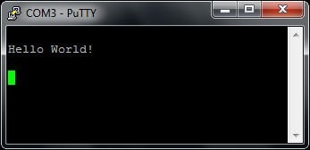
Arm® GCCを使用する
ツールチェーンのセットアップ
ここでは、Kinetis SDKでサポートされているように、Arm GCCツールチェーンを使用してKSDKデモ・アプリケーションのビルドと実行を行う際に必要となるコンポーネントをインストールする手順について説明します。Arm GCCツールの使用方法はさまざまですが、今回の例では、Windows環境に焦点を当てています。ここでは省略しますが、GCCツールは、Linux OSやMac OS Xの環境でも利用できます。
GCC Arm Embeddedツールチェーンのインストール
GNU Arm Embeddedツールチェーンからインストーラをダウンロードして、実行します。これは実際のツールチェーンです(コンパイラ、リンカなど)。Kinetis SDKリリース・ノートに記載されている、サポート対象の最新バージョンのGCCツールチェーンを使用する必要があります。
MinGWのインストール
MinGW (Minimalist GNU for Windows) 開発ツールは、サード・パーティ製のCランタイムDLL(Cygwinなど)に依存しないツール・セットを提供します。KSDKで使用されているビルド環境ではMinGWビルド・ツールを利用せず、MinGWとMSYSのベース・インストールを活用しています。MSYSは、Unix系のインターフェースと各種ツールを備えた基本シェルを提供します。
- MinGW - Minimalist GNU for Windowsファイルから最新のMinGW mingw-get-setupインストーラをダウンロードしてください
- インストーラを実行します。インストール・パスとしては「C:\MinGW」を推奨しますが、他のどの場所にでもインストールできます
- [Basic Setup(基本セットアップ)]で、「
mingw32-base」と「msys-base」が選択されていることを確認します。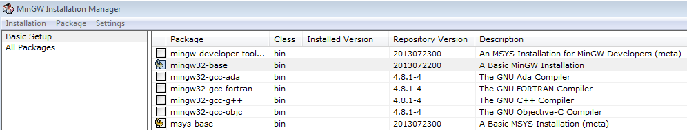
- [Installation(インストール)]メニューで[Apply Changes(変更を適用)]をクリックし、残りの手順に従ってインストールを完了します。
-
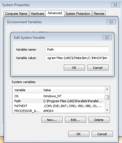
Windows OSのPath環境変数に適切なアイテムを追加します。これは、[Control Panel(コントロール・パネル)]>[System and Security(システムとセキュリティ)]>[System(システム)]>[Advanced System Settings(システムの詳細設定)]の[Environment Variables...(環境変数)]セクションで設定します。パスは次のとおりです。
\bin デフォルトのインストール・パスであるC:\MinGWを使用した例を以下に示します。パスが正しく設定されていないと、ツールチェーンは機能しません。
-
CMakeからCMake 3.0.xをダウンロードします
-
CMakeをインストールします。インストール時には、必ず[Add CMake to system PATH(CMakeをシステムPATHに追加)]オプションを選択します。すべてのユーザーが使用できるパスにインストールするか、現在のユーザーのみが使用できるパスにインストールするかは、ユーザーが選択します。今回の例では、すべてのユーザーに対してインストールしています。
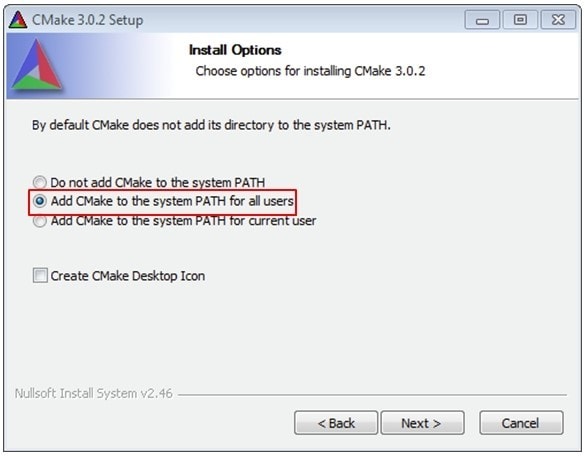
- インストーラの残りの手順に従います
- PATHの変更を適用するには、システムの再起動が必要になる場合があります
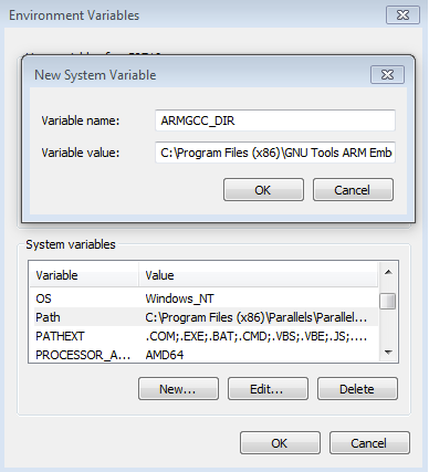
ARMGCC_DIR向けの新しい環境変数を追加する
新しいシステム環境変数を作成して、「ARMGCC_DIR」という名前を付けます。この変数の値で、Arm GCC Embeddedツールチェーンのインストール・パスを指定します。今回の例では、次のようになります。
C:\Program Files (x86)\GNU Tools Arm Embedded\4.9 2015q3 インストール・フォルダの正確なパス名については、GNU Arm GCC Embeddedツールのインストール・フォルダを参照してください。
CMakeのインストール
サンプル・アプリケーションのビルド
サンプル・アプリケーションをビルドする手順は次のとおりです。
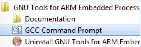
- GCC ARM Embeddedツールチェーンのコマンド・ウィンドウが開いていない場合はここで開きます。ウィンドウを開くには、Windows OSの[スタート]メニューから、[プログラム]>[GNU Tools ARM Embedded
]に移動して、[GCC Command Prompt(GCCコマンド・プロンプト)]を選択します。 -
サンプル・アプリケーションのプロジェクト・ディレクトリに移動します。パスは次のようになります。
/boards/ / / /armgcc このガイドの場合、実際のパスは次のようになります。
/boards/evkMIMXRT1040/demo_apps/hello_world/armgcc 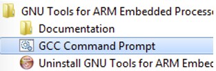
-
コマンドラインで「
build_flexspi_nor_debug.bat」と入力するか、Windows OSのエクスプローラで「build_flexspi_nor_debug.bat」ファイルをダブルクリックして、ビルドを実行します。次のような出力画面が表示されます。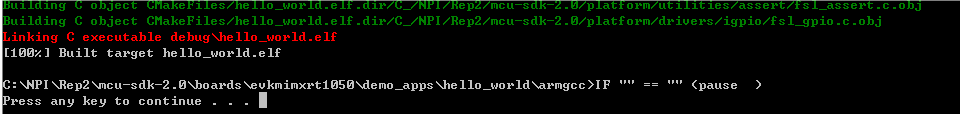
サンプル・アプリケーションの実行
ここでは、J-Link GDBサーバ・アプリケーションを使用してデモ・アプリケーションを実行する手順について説明します。この作業を行うには、次の2つの要件があります。
- 以下のいずれかであることを確認してください。
- ボードのOpenSDAインターフェースが、J-Link OpenSDAファームウェアでプログラムされている。ボードがOpenSDAをサポートしていない場合は、スタンドアロンのJ-Linkポッドが必要になります
- ボードのデバッグ・インターフェースにスタンドアロンのJ-Linkポッドが接続されている。一部のハードウェア・プラットフォームでは、外部デバッグ・インターフェースで正常に機能させるためにハードウェアに変更を加える必要があることにご注意ください
J-Linkインターフェースを設定して接続したら、以下の手順に従ってデモ・アプリケーションをダウンロードして実行します。
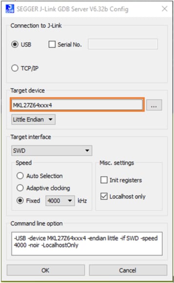
- このボードはJ-Linkデバッグ・プローブをサポートしています。ご使用の前にSEGGERソフトウェアをインストールしてください。SEGGERホームページからダウンロードできます
- 開発プラットフォームをPCに接続します。OpenSDAのUSBコネクタとPCのUSBコネクタをUSBケーブルでつないでください。スタンドアロンのJ-Linkデバッグ・ポッドを使用している場合は、ボードのSWD/JTAGコネクタにも接続してください
- PCのターミナル・アプリケーション(PuTTY、Tera Termなど)を開き、デバッグのシリアル・ポート番号に接続します。次の設定値を用いてターミナルを設定します。
- ボーレート115200(
board.hファイルのBOARD_DEBUG_UART_BAUDRATE変数を参照) - パリティなし
- 8データ・ビット
- 1ストップ・ビット
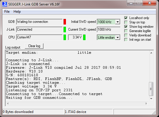
J-Link GDBサーバ・アプリケーションを開きます。SEGGERインストール・フォルダ(例えば、C:\Program Files (x86)\SEGGER\JLink_V616f)に移動します。デバッグおよびリリースのターゲットについては、ここでコマンド・ウィンドウを開き、「JLinkGDBServer.exe」コマンドを使用します。
サンプル・アプリケーションの出力を格納するディレクトリに移動します。出力は、選択したビルド・ターゲットに応じて、次のいずれかのパスに格納されます。
/boards/// /armgcc/debug /boards/// /armgcc/release 今回の例の場合、実際のパスは次のようになります。
/boards/evkMIMXRT1040/demo_apps/hello_world/armgcc/debug arm-none-eabi-gdb.exe .elf 」というコマンドを実行します。この例の場合、「arm-none-eabi-gdb.exe hello_world.elf」というコマンドになります。 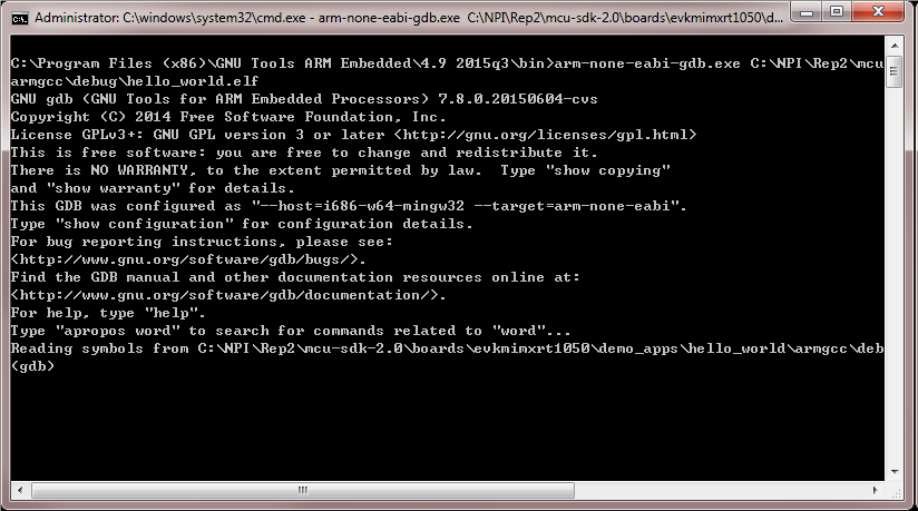
次のコマンドを実行します。
「target remote localhost:2331」
「monitor reset」
「monitor halt」
「load」
hello_worldアプリケーションが実行され、ターミナルにバナーが表示されます。表示されない場合は、ターミナルの設定と接続を確認してください。
ブート・オプション
i.MX RTファミリでサポートされているさまざまなブート・ソースについて詳しく説明しています。これには、Execute in Place (XIP) も含まれます。
i.MX RTクロスオーバーMCU向けブート・オプション
セキュリティ
i.MX RTセキュア・ブート・ラボ・ガイド - i.MXファミリのセキュア・ブート機能の使用方法について説明しています。これには、キーペアと証明書の生成、leftosbツールを使用したヒューズのプログラム、ファームウェアの署名などの方法が含まれます。
今日のセキュリティ要件を満たす:クロスオーバー・プロセッサでエンド・ツー・エンドのセキュリティを実現 - IoTのエンド・ノードとエッジ・ノードが満たすべき共通のセキュリティ目標と、エンド・デバイスで信頼の基点を実現するために必要な手順やツールについて説明します。
ワンストップ・セキュア・ブート・ツール:NXP-MCUBootUtility v1.0.0のリリース - NXP-MCUBootUtilityは、NXP MCUセキュア・ブート用に特別に設計されたGUIツールです。NXPの公式セキュリティ・イネーブルメント・ツールセットのすべての機能が含まれており、グラフィカル・ユーザー・インターフェースの完全な動作をサポートします。
外部メモリ
QSPIフラッシュからのブートを可能にする方法 - このドキュメントでは、フラッシュ・ローダでOpen SDAまたはMfgToolを使用してブータブル・イメージを外部ストレージ・デバイスにプログラムする手順を説明しています。
FLEXSPI NORフラッシュのデバッグを可能にする方法 - このアプリケーション・ノートでは、新しいFLEXSPI NORフラッシュをプログラム、デバッグ、および設定する方法について説明しています
Adesto EcoXipメモリを使用したコードの開発 - NXP i.MX RT1050 EVKボードとAdesto EcoXiPフラッシュ・デバイスを組み合わせて設定するためのハードウェアおよびソフトウェア要件について説明しています。
モータ制御
i.MX RTでモータを回転させる - このプレゼンテーションでは、BLDCモータ、PMSMモータ、ACIMモータを回転させるためのMCUの要件、モータ制御の基本およびフレームワーク、i.MX RTでのモータ制御の実装方法をご紹介します。
MIMXRT10xx EVKでのPMSMフィールド指向制御のアプリケーション・ノート - 三相永久磁石同期モータ (PMSM) 向けの、センサ使用またはセンサレスの速度/位置モータ制御ソフトウェアの実装について説明しています。
MIMXRT10xx EVKでのPMSMフィールド指向制御のユーザー・ガイド - IAR Embedded Workbench®、MCUXpresso、Vision® Keil® IDEなど、ほとんどの一般的なIDEにおける永久磁石同期モータ (PMSM) プロジェクトのオープン、コンパイル、デバッグ、実行の方法をステップ・バイ・ステップで紹介するガイド。また、NXPのFreedom PMSMパワー・ステージおよびi.MX RT10xx評価キットを完全なモータ制御リファレンス・デザインに変える方法、ならびにモータ制御アプリケーションを制御するためのFreeMASTER GUIツールの初期化について説明しています。
機械学習
i.MX RTでのeIQ®転移学習ラボ - モデルに対して転移学習を実行し、i.MX RT1040プラットフォームでそのモデルを実行する方法を紹介しています。
i.MX RT向けeIQ Glowラボ - 手書き数字の認識モデルのサンプルを実行して、Glowニューラル・ネットワーク・コンパイラ・ツールの使用方法を学びます。以下に、このラボのステップ・バイ・ステップ・ビデオを紹介しています
Glowニューラル・ネットワーク・コンパイラのスタート・ガイド:
グラフィックス
NXP MCUと組込みウィザードを使用したリアルタイム・インダストリアルHMIシステムへのグラフィックスの実装 - NXPはTARA Systemsと連携し、組込み型ウィザードをイネーブリング・ソフトウェア・テクノロジとして提供しています。i.MX RT1040向けMCUXpresso SDKでは、完全に統合された組込み型ウィザードのサンプル・プロジェクトが提供されています。
組込み型ウィザードとMCUXpressoのスタート・ガイド - 組込み型ウィザードを含むSDKをダウンロードして、サンプル・プロジェクトをデバイスで起動して実行する方法について説明しています。
i.MX RT10xx MCUとCrank Storyboardを使用したリアルタイム・インダストリアルHMIシステムへのグラフィックスの実装 - NXPはCrank Softwareと連携し、Storyboardをイネーブリング・ソフトウェア・テクノロジとして提供しています。i.MX RT1040向けMCUXpresso SDKでは、完全に統合されたStoryboardのサンプル・プロジェクトが提供されています。
Wi-Fi®
i.MX RTプラットフォームを使用したNXP Wi-Fiモジュールのスタート・ガイド - Wi-Fiモジュールの動作テストを行いましょう。このガイドでは、Wi-Fiモジュールとi.MX RTプラットフォームを使用します。
Tera Termチュートリアル
Tera Termチュートリアル
Tera Termは、広く利用されているオープン・ソースのターミナル・エミュレーション・アプリケーションです。このプログラムを使用して、NXP開発プラットフォームの仮想シリアル・ポートから送信された情報を表示できます。
- SourceForgeからTera Termをダウンロードします。ダウンロードしたら、インストーラを実行し、このウェブページに戻って手順を続行します
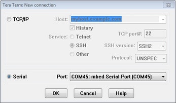
- Tera Termを起動します。初めて起動する際には、次のダイアログが表示されます。シリアル・オプションを選択します。ボードが接続されている場合は、COMポートが自動的にリスト内に表示されます
- 事前に確認したCOMポート番号を使用して、シリアル・ポートをボーレート115200、8データ・ビット、パリティなし、1ストップ・ビットに設定します。この設定は[Setup(セットアップ)]>[Serial Port(シリアル・ポート)]から行うことができます
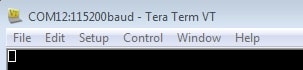
- 接続が確立されているか検証します。確立されている場合、Tera Termのタイトル・バーに次のように表示されます
- 以上で設定は完了です
PuTTYチュートリアル
PuTTYチュートリアル
PuTTYは、広く利用されているターミナル・エミュレーション・アプリケーションです。このプログラムを使用して、NXP開発プラットフォームの仮想シリアル・ポートから送信された情報を表示できます。
- 下のボタンをクリックしてPuTTYをダウンロードします。ダウンロードしたら、インストーラを実行し、このウェブページに戻って手順を続行します。
- 選択したダウンロードのタイプに応じて、ダウンロードした*.exeファイルをダブルクリックするか、[Start(スタート)]メニューから選択して、PuTTYを起動します。
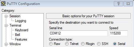
- 表示されたウィンドウで設定を行い、[Serial(シリアル)]ラジオ・ボタンを選択して、事前に確認したCOMポート番号を入力します。ボーレートもあわせて指定します。今回は「115200」を入力します。
- [Open(開く)]をクリックして、シリアル接続を確立します。ボードが接続されていて、正しいCOMポートが入力されていれば、ターミナル・ウィンドウが開きます。設定が正しくない場合は、アラートが表示されます。
- 以上で設定は完了です
設計・リソース
ソフトウェア
- i.MX RT1040向けMCUXpressoソフトウェア開発キット (SDK) - MCUXpresso SDKについて、およびお使いのプロセッサや評価ボードに合わせてSDKを特別にカスタマイズおよびダウンロードできるSDK Builderについて説明しています。
サポート
設計のヒントやトレーニング・ドキュメント、さらにNXPコミュニティを通じて、RT1040についての知識を深めることができます。不明な点がある場合は、NXPサポートにお問い合わせください。
設計のヒント
i.MX RTクロスオーバーMCU向けハードウェア設計のヒント - 初めてのi.MX RT1040の設計を順調に開始するために役立つヒント。パワー・マネジメント・ユニット、さまざまなブート・モード、設定オプションの使用などを含みます。
トレーニング
- MCUXpressoソフトウェアおよびツールの概要 - MCUXpresso SDK、IDE、およびConfig toolsのスタート・ガイド。
- 今日のセキュリティ要件を満たす:クロスオーバー・プロセッサでエンド・ツー・エンドのセキュリティを実現 - IoTのエンド・ノードとエッジ・ノードが満たすべき共通のセキュリティ目標と、エンド・デバイスで信頼の基点を実現するために必要な手順やツールについて説明します。
- i.MX RTでモータを回転させる - このプレゼンテーションでは、BLDCモータ、PMSMモータ、ACIMモータを回転させるためのMCUの要件、モータ制御の基本およびフレームワーク、i.MX RTでのモータ制御の実装方法をご紹介します。
- i.MX RTでのグラフィックの作成方法 - i.MX RTでのグラフィックス開発の方法について説明しています。i.MX RTは、GUI向けの高度なマルチメディアを使用した製品設計と、拡張されたヒューマン・マシン・インターフェース (HMI) エクスペリエンスをサポートします。
- i.MX RTでの音声ソリューション - MCUのAlexa音声ソリューションの機能、アーキテクチャ、コスト、および使いやすさの利点についてご紹介します。このセッションでは、Wi-Fiを使用したオンボードAlexaの実際の使用方法、ならびにコスト効率の高い遠距離実装を使用したAlexaとのやり取りについて紹介します。
- i.MX RTでの初めてのZephyrアプリケーションのビルド - i.MX RTでZephyrプロジェクトを開始する方法を学びます。Zephyrビルド環境で実践的体験を得て、初めてのZephyrアプリケーションをボードにプログラムします。
コミュニティ
NXPのいずれかのコミュニティ・サイトで、他のエンジニアとつながり、i.MX RTクロスオーバーMCUを使用した設計に関する専門的なアドバイスを受けることができます。