2-in-1 DC-DCおよびBMSの概念実証のスタート・ガイド
このドキュメントの内容
-
パッケージの内容
-
ソフトウェアの入手
-
接続
-
ビルドとロード
サインイン 進行状況を保存するには アカウントをお持ちでない方 アカウントを作成する。
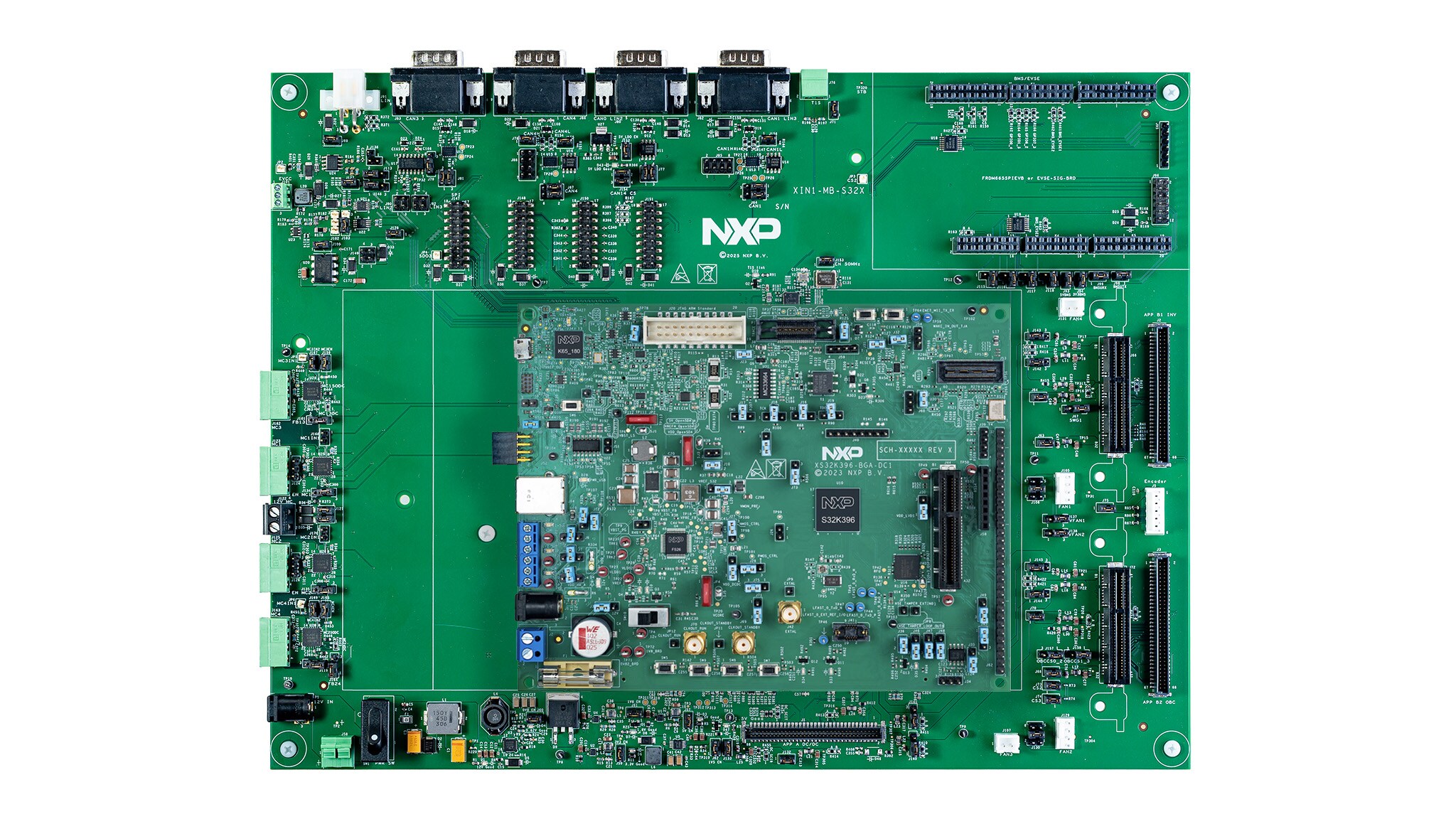
お客様の X-IN-1アプリケーション向けS32K396評価マザーボード
1. パッケージの内容
電動化X-in-1プラットフォームは、複数の車両電動化アプリケーションを1つの電子制御ユニット (ECU) に統合したものです。このプラットフォームによって従来は別々のECUが必要だった機能を統合できるため、ハードウェアの複雑さを減らし、システム・コストと重量を削減しながら、安全性とセキュリティの管理を高い効率性でサポートできます。
このスタート・ガイドでは、2-in-1 DC-DCコンバータとバッテリー・マネジメント・システム (BMS) の概念実証 (POC) をセットアップして構築し、実行する方法について説明します。どちらのアプリケーションも、S32K396マイクロコントローラ (MCU) を使用して共有プラットフォーム上で実行します。
1.1 キットのコンポーネント
キットには以下のものが含まれています。
- NXP S32K39評価ボード (EVB) (S32K396-BGA-DC1)
- NXP S32K3マザーボード (XIN1-MB-S32X)
- アプリケーション・ボードを接続するためのケーブル:
- NXP XIN1-CABLE6またはXIN1-CABLE12
- 標準の68ピン1.27 mmピッチのリボン・ケーブル(M55-8006842-0150AまたはM55-8006842-0300Aなど)
- NXP DC-DCコンバータ・アプリケーション・ボード (XIN1-DC-DC-LV)
- BMSアプリケーション・ボード:
- NXPトランスポート・プロトコルリンク (TPL) ブリッジ (FRDM665SPIEVB)
- NXP BMSセル・モニタリング・ユニット (CMU) (RD33774PC3EVB)
- NXP 18セル・バッテリパック・エミュレータ (BATT-18EMULATOR)
- NXP BMSバッテリー・ジャンクション・ボックス (BJB) (RDA777T2)
- NXP BJBエミュレータ (PACK-BJBEMUL)
1.2 その他の機材
電力を供給するために、次の機器が必要になります。
- 48 V電源
- DC-DCコンバータの負荷は、電子的な負荷または抵抗負荷にすることができます
1.3 最小システム要件
評価を行うには、NXP FreeMASTERの最小システム要件を満たしたWindows PCまたはLinux PCが必要です。
2. ソフトウェアの入手
この手順では、必要なソフトウェア・ライブラリがインストールされていることと、それが本プロジェクトに含まれる他のソフトウェア・コンポーネントと互換性があることを確認してください。こうしたライブラリの一部が既にPCにインストールされている場合があります。
2.1 AMMCLIB 1.1.40のセットアップ
インストール・プロセスの最初の手順で.exeファイルを正常にダウンロードできたら、デフォルトのパスを次のように変更します。
C://S32DS.3.6.0/S32DS/software/ - S32 Design Studio (DS) を起動し、[Help(ヘルプ)]をクリックします
- S32DSの[Extensions and Updates(拡張機能と更新)]をクリックします
- 次に、[Manage Sites(サイトの管理)]をクリックします
- 次に、[Available S32DS Software Sites(利用可能なS32DSソフトウェア・サイト)]にエントリを追加して
- AMMCLIBという名前を付けます
- リンク先は以下の通りです。
http://www.nxp.com/lgfiles/updates/Eclipse/AMMCLIB/S32DS_3.5
- [Apply(適用]をクリックした後、[Close(閉じる)]をクリックします
- AMMCLIB 1.1.40更新サイトがオプションとして表示されます

2.2 プラットフォーム間通信フレームワーク (IPCF) のセットアップ
この手順では、S32DSのIPCF用のアップデートサイトをインストールします。
tresos StudioでIPCFを使用するには、次の手順に従います。
SW32K396_IPCF_1.1.0_D2502.exeを実行してアプリケーションをインストールします- 次の場所に移動します
/X-in-1/eenvs/S32K396/2-in-1_DC-DC_FoxBMS/M7_2_MSC/S32K396_SSM_core2/util - makeフォルダをコピーします。ここには、必要な2つのIPCF makefileが含まれています
- makeフォルダをIPCFインストール・フォルダ内の次のディレクトリに貼り付けます。
SW32K396_IPCF_1.1.0_D2502/eclipse/plugins/Ipcf_TS_T40D34 M11I0R0 plugin.xmlファイルを開きます- 59行目と60行目をコメントアウトします
2.3 FreeMASTERドライバのセットアップ
S32 DSとFreeMASTERをインストールした後、Tresos Studioを使用して、構築されたマスタ・セーフティ・コアにソースファイルをリンクさせます。
Tresos Studioでプロジェクトを開き、次の手順に従います。
- 次の場所に移動します。
/X-in-1/eenvs/S32K396/2-in-1_DC-DC_FoxBMS/M7_2_MSC/S32K396_SSM_core2/util - 次に、
common.makを開きます -
次の行を探します。

- 図1に示すように、既存のパスをFreeMASTERドライバ・ソースへのパス(例:
S32DS.3.6.0/S32DS/software/FreeMASTER_S32K3_v3.0/src)に置き換えます
2.4 セーフティ・ソフトウェア・フレームワーク (SAF) EVAL ドライバのセットアップ
.exeファイルを使用してSW32K3_SAF_1.0.5_EVAL_D2502ドライバをインストールした後、以下の手順を実行します。
-
C:/EB/tresos/plugins/から、以下のプラグインを削除します。Bist_TS_T40D34M10I5R0eMcem_TS_T40D34M10I5R0mSel_TS_T40D34M10I5R0Safetybase_TS_T40D34M10I5R0sBoot_TS_T40D34M10I5R0sCheck_TS_T40D34M10I5R0sReco_TS_T40D34M10I5R0
- 次に、Bashターミナルを開いて以下のコマンドを実行します。
cd C://build/ export S32K39X_EB_ACP_DIR=C:/EB/tresos/export S32K3_SAF_DIR=C:/NXP/SW32K3_SAF_1.0.5_EVAL_D2503/eclipse/pluginspython build_instance.py -c ../X-in-1/build.json --patch all
3. 接続
3.1 接続
この手順では、ビルド済みのバイナリを実行できるよう準備しておくか、ソースから電動化X-in-1プロジェクトをビルドします。
提供されているビルド済みバイナリを使用して電動化X-in-1プロジェクトを実行するには、必要なデバッグ・ツールをインストールし、NXPソフトウェア・カタログにサインインします。ソースからプロジェクトをビルドする場合を除き、ビルド依存関係をインストールする必要はありません。
電動化X-in-1プロジェクトをソースからビルドするには、以下の手順に従います。
- NXPソフトウェア・カタログにサインインします
- 自分のアカウントから、必要な製品カタログとソフトウェア・リリースにアクセスできることを確認します
- NXP Package Managerバンドル・インストーラをダウンロードします
- バンドル・インストーラを実行して、次のどちらかのインストール方法を選択します。
- ワンクリック・インストール:バンドル・インストーラに付属の事前構成済みスクリプトを使用して、必要なソフトウェア・リリースをインストールします
- 手動インストール:依存関係を1つずつ個別にインストールできます
- アクティベーションが必要なソフトウェアについては、ダウンロードしたバンドル・インストーラに付属するユーザー・マニュアルの指示に従って、必要なアクティベーション・コードを取得し、入力してください。
4. ビルドとロード
4.1 ビルドとロード
ラボ・ベンチのセットアップ方法については、以下の図2に示す例を参照してください。
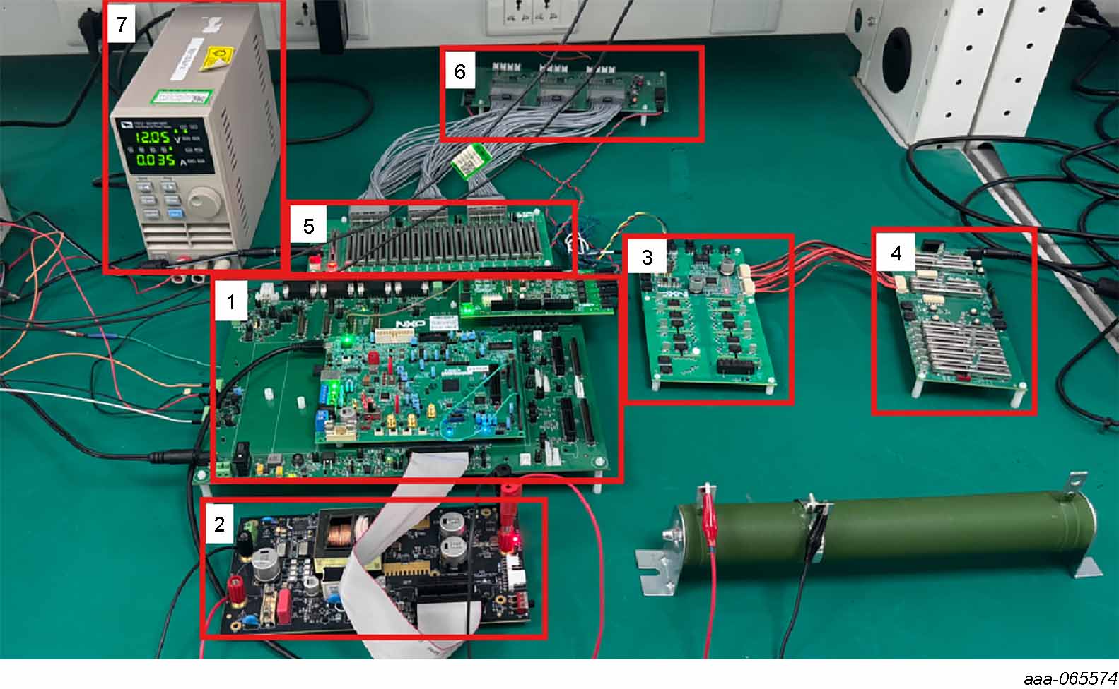
上の画像内の番号ラベルは、以下のリスト内の同じ番号の項目と対応しています。
- アセンブリ:
- XIN1-MB-S32Xマザーボード
- S32K396-BGA-DC1拡張ボード
- S32K396 1P40E電子制御ユニット (ECU)
- FRDM665SPIEVBトランスポート・プロトコル・リンク (TPL) ゲートウェイ・ボード
- XIN1-DC-DC-LVDC-DCアプリケーション・ボード
- RDA777T2 BMS BJBボード
- PACK-BJBEMUL BJBエミュレータ
- RD33774PC3EVB BMS CMUボード
- BATT-18EMULATOR 18セル・バッテリパック・エミュレータ
- 電源
設計・リソース
関連リソース
「X-IN-1モジュール型プラットフォーム設計」ページに加えて、関連するハードウェアおよびソフトウェアのページも参照してください。