汎用車載向けFRDM S32K344開発ボードのスタート・ガイド
サインイン 進行状況を保存するには アカウントをお持ちでない方 アカウントを作成する。
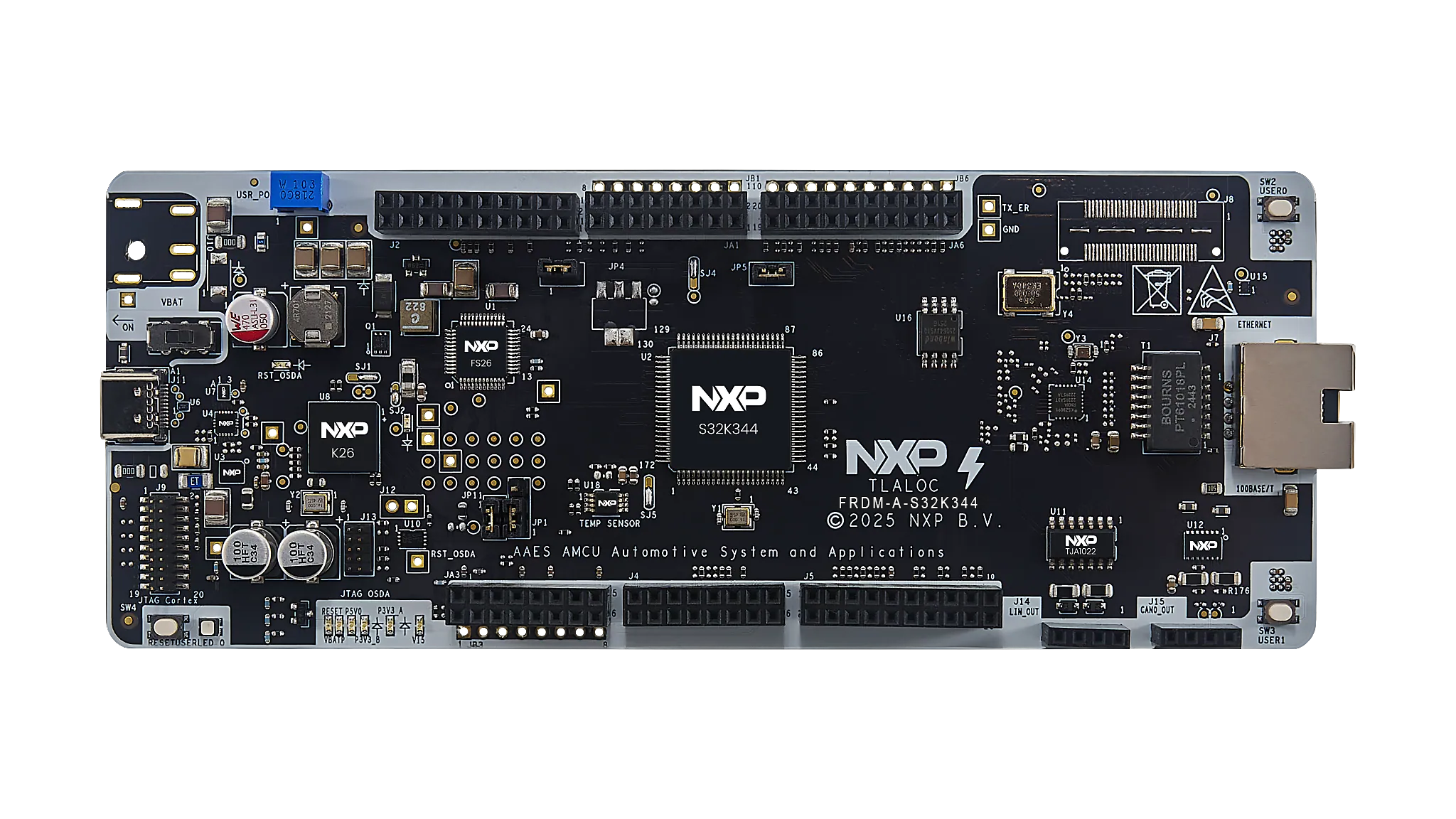
お客様の 車載向けFRDM S32K344開発ボード
1. パッケージの内容

2. ソフトウェアの入手
資格情報を使用してNXPにサインインします。
2.1 ソフトウェアのインストール
- FRDM Automotive Bundleのリンクからソフトウェア・バンドルへ移動します
- [Generate(生成)]をクリックしてダウンロードします
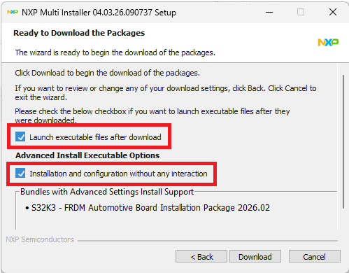
- NXP Multi Installerを実行します
- デスクトップに作成されたショートカットからS32 Design Studio for S32 Platform 3.6.5を起動します
「Launch executable after download(ダウンロード後に実行可能ファイルを起動する)」と「Installation and configuration without any interaction(操作を一切行わずにインストールおよび構成する)」を選択すると、FRDMバンドルと利用可能なすべてのコンポーネントが一緒にインストールされます。
すべてのソフトウェアが自動でインストールおよび構成されました。
3. 接続
3.1 電源の接続
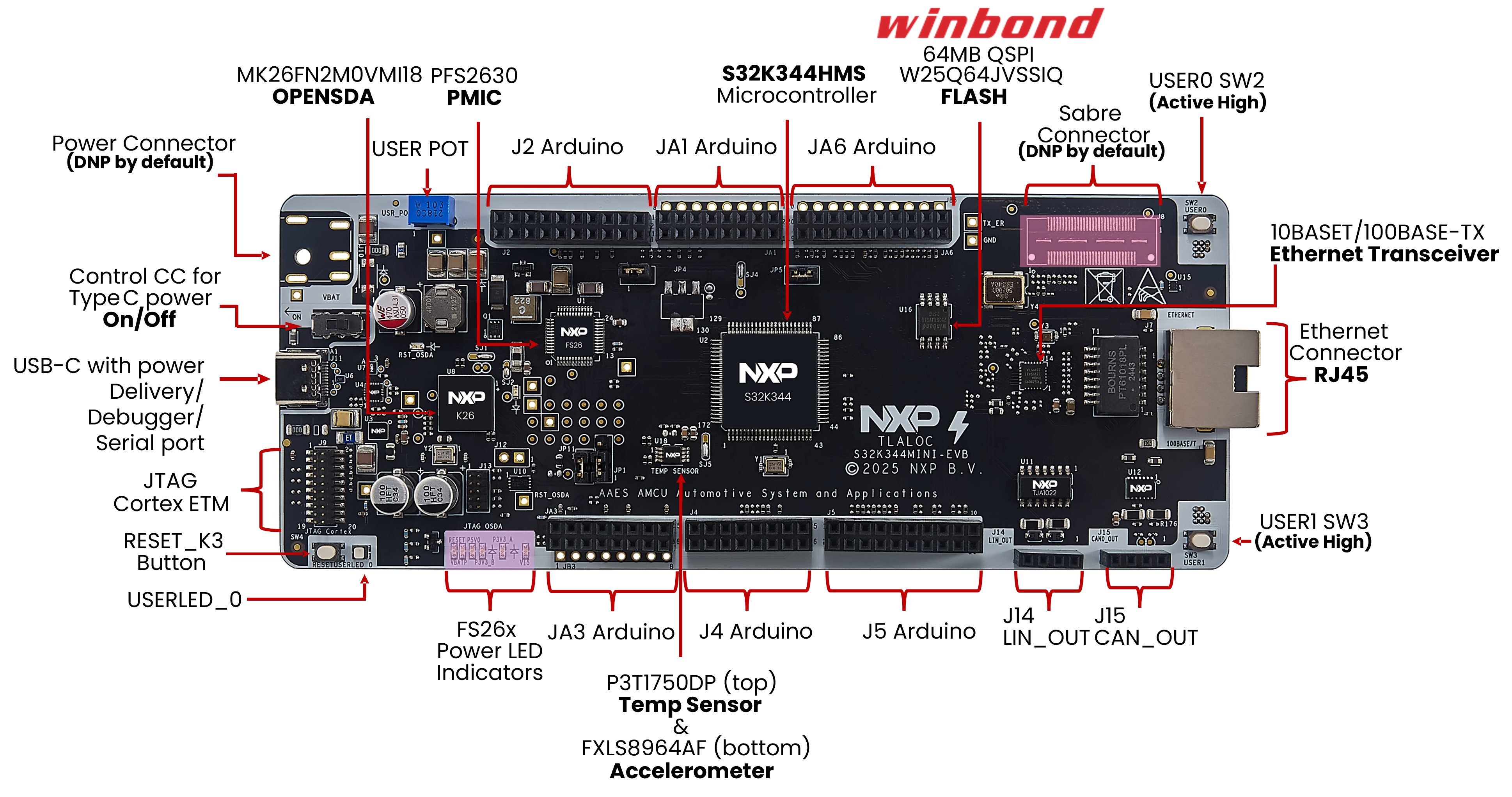
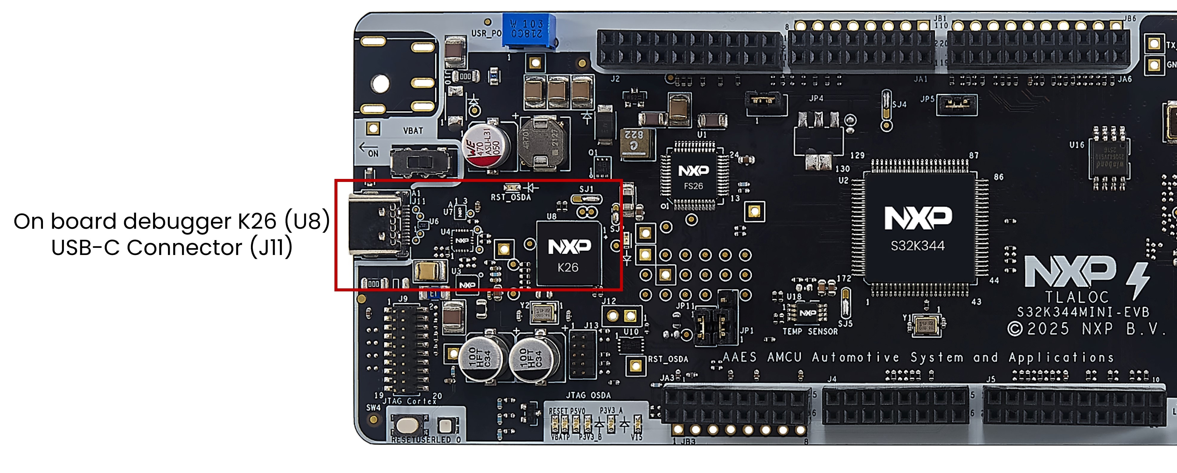
FRDM-A-S32K344は、S32K344EVB-Q172をベースにしたラピッド・プロトタイピング・ボードです。このボードは本番環境での使用を目的としていないため、主な電源供給方法はUSB Power Delivery経由となり、FS26 SBCに接続します。
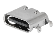
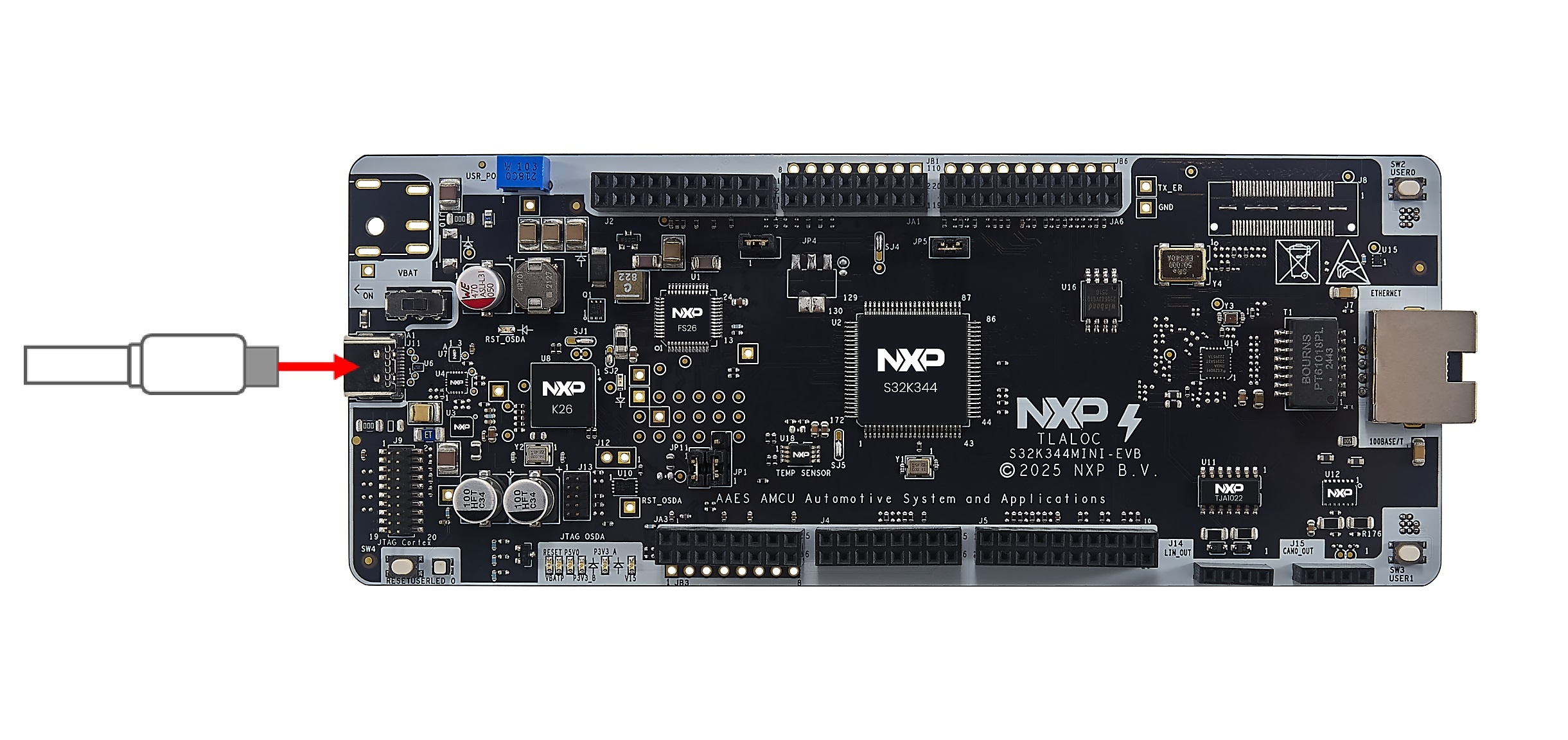
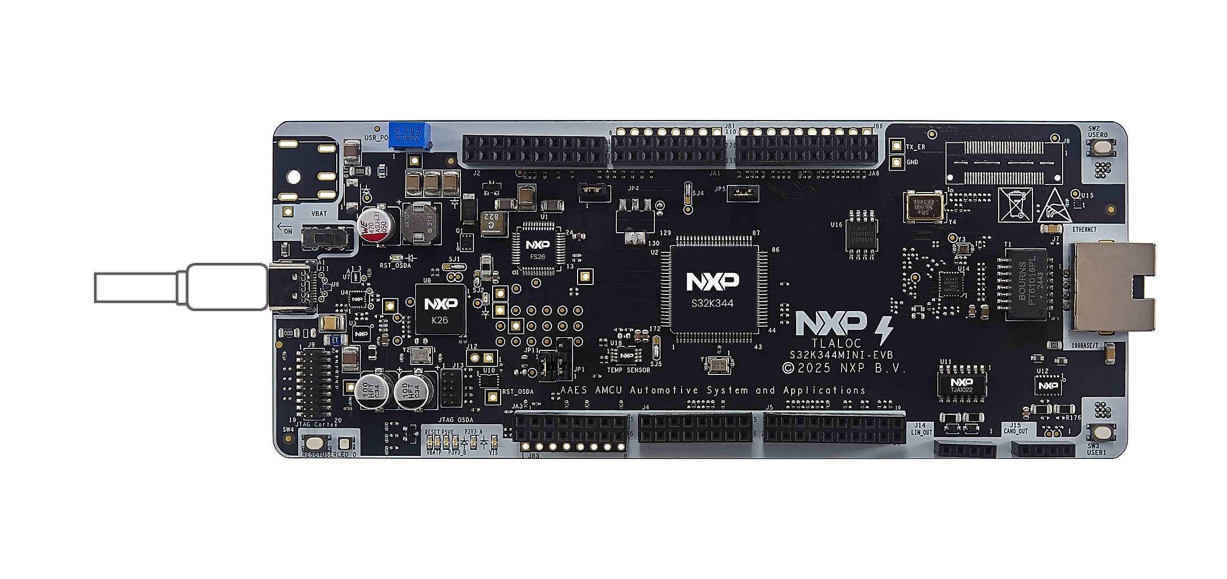
デフォルトでは、FRDM-A-S32K344はJ11 USB-Cコネクタを介して給電されます。ボードのすべての機能を正常に使用するために、パッケージに含まれているUSB-Cケーブルか、USB Power Delivery (PD) をサポートするケーブルを使用することをお勧めします。非準拠のケーブルを使用すると、供給される電流が制限され、性能が低下する恐れがあります。
ボードに適切に給電するには、USB-C PD充電器やPD対応のノートパソコンなど、USB-C PD対応電源が必要です。最近のノートパソコンのほとんどはUSB PDに対応していますが、ご使用前にお使いのノートパソコンの仕様を確認してください。
FRDM-A-S32K344は20 Vまでの入力電圧に対応していますが、FS26 SBCの推奨事項に基づき、9 V、12 V、15 Vのいずれかの電圧範囲内で、1 A以上で動作させることが推奨されます。この電圧と電流を確保するには、USB PD電源とPD PHY (PTN5110) の間での適切なネゴシエーションが必要となります。S32K344でこのネゴシエーションを実装する方法については、最寄りのNXPのFAEにお問い合わせいただくか、NXPアプリケーション・コード・ハブのウェブサイトで公開されているコードを参照してください。
3.2 起動シーケンス
- USB-Cケーブルを
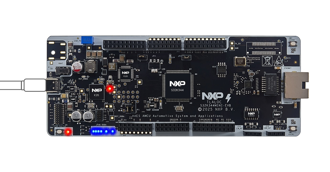
J11コネクタに接続してボードに給電します - ボードの電源を入れるには、スイッチSW5のデフォルトの位置を2-3設定に変更します
- ボード上のすべての電源LEDが点灯していることを確認します
4. ビルドと実行
4.1 ビルドと実行
開発を加速するには、アプリケーション・コード・ハブをご覧ください。
アプリケーション・コード・ハブでは、以下のことが可能です。
- 検証済みの広範なアプリケーション・サンプルへのアクセス
- 迅速なプロトタイピングのためのすぐに使えるソフトウェアのダウンロード
- 現行の設計ガイドラインやベスト・プラクティスに従ったテスト済みコード資産の活用
設計・リソース
チップに関するドキュメント
サポート
トレーニング
フォーラム
NXPのコミュニティ・サイトで、他のエンジニアとつながり、FRDM-A-S32K344開発ボードを使用した設計に関する専門的なアドバイスを受けることができます。