Getting Started with the PCF8525-ARD Evaluation Board
このドキュメントの内容
-
Out of the Box
-
Get Hardware
-
Install Software
-
Configure Hardware
サインイン 進行状況を保存するには アカウントをお持ちでない方 アカウントを作成する。
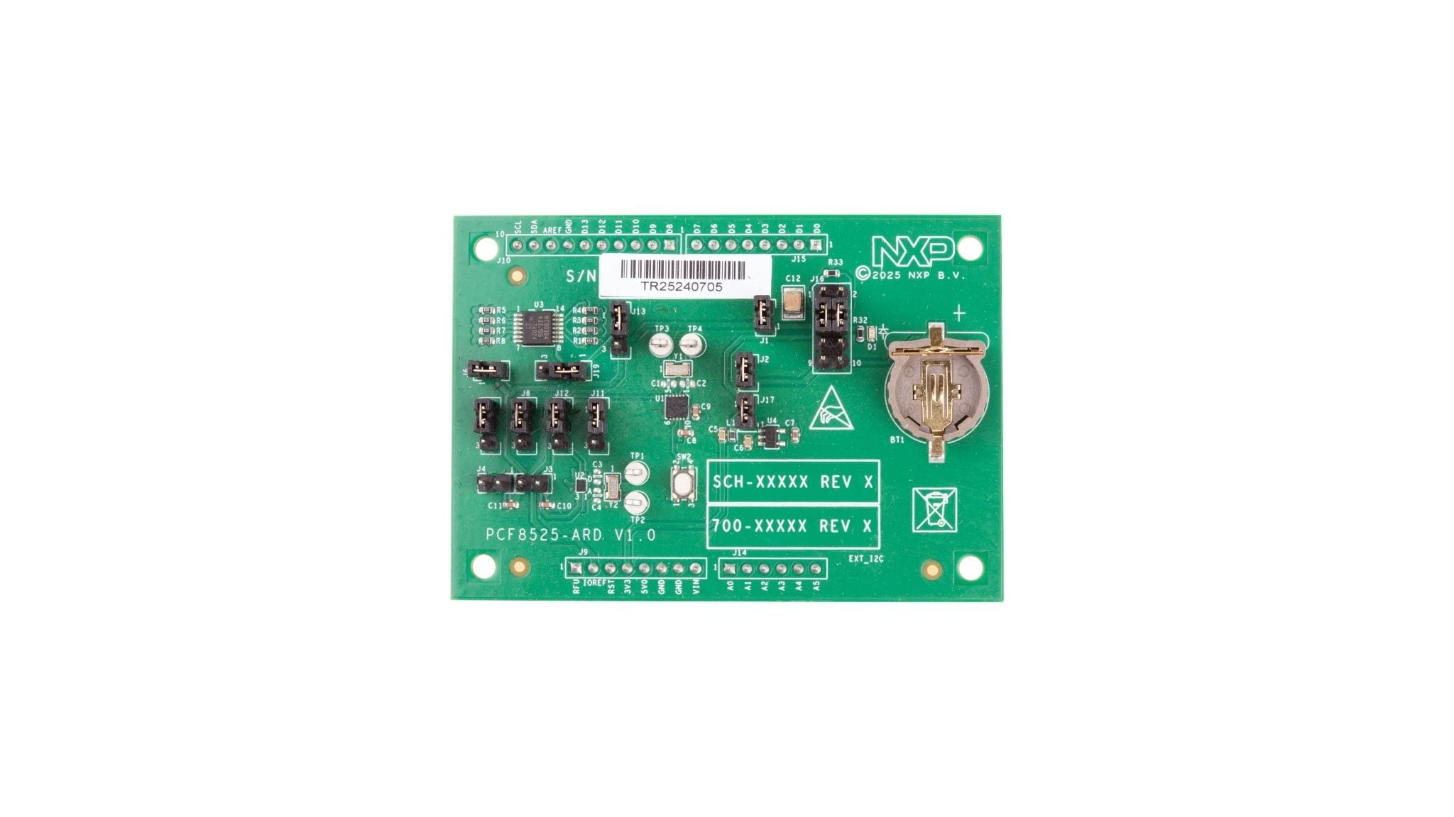
お客様の PCF8525-ARD Arduino® Shield Evaluation Board
1. Out of the Box
The NXP analog product development boards provide an easy-to-use platform for evaluating NXP products. The boards support a range of analog, mixed-signal and power solutions. They incorporate monolithic integrated circuits and system-in-package devices that use proven high-volume technology. NXP products offer longer battery life, a smaller form factor, reduced component counts, lower cost and improved performance in powering state-of-the-art systems.
This page will guide you through the process of setting up and using the PCF8525-ARD evaluation board.
1.1 Kit Contents
The kit contents include:
- Assembled and tested the evaluation board in an antistatic bag
- Quick Start Guide
1.2 Assumptions
Familiarity with the I²C bus is helpful but not required.
1.3 Minimum System Requirements
This evaluation board requires a Windows PC workstation. Meeting these minimum specifications must produce good results when working with this evaluation board.
- Computer with Windows 10 or 11
- One USB port (either 3.0 or 2.0 or 1.1 compatible)
- One FRDM-MCXN947 MCU EVK along with the associated firmware/GUI software
- USB cable for power and data connection between PC and EVK board
2. Get to Know the Hardware
2.1 Board Features
- Contains both versions of PCF8525: PCF8525UK (WLCSP) or PCF8525TK (HVSON)
- Onboard jumpers to select between PCF8525UK (WLCSP) or PCF8525TK (HVSON)
- Equipped with Arduino Uno R3 port for direct connection with Arduino devices
- Onboard battery holder for battery switch-over circuit test
- Onboard connector and switches for timestamp function tests
- Fully compliant with FRDM-MCXN947 EVK board, including GUI (Windows 10 or 11)
2.2 Board Description
The evaluation board is built around the PCF8525, a Real-Time Clock (RTC) IC. It features an integrated Temperature Compensated Crystal Oscillator (TCXO) optimized for high accuracy and ultra-low power consumption.
The PCF8525 has an I²C-bus, a backup battery switch-over circuit, a programmable watchdog function, timestamp function and other features. For more details, see the Nano-Power RTC IC with I²C Interface and Temperature Compensation (document PCF8525) data sheet.
The PCF8525-ARD works as an expansion card, which can be connected through an Arduino port to various Arduino compatible (including original Arduino UNO R3) boards. The board is equipped with a battery holder allowing the user to test the battery switch-over circuit of the RTC. The evaluation board is intended to test and evaluate all characteristics of the silicon. These characteristics include I²C communication, power management, battery backup, timestamps, interrupts, and other internal features of the PCF8525 RTC.
Additionally, the expansion board has software support and a graphical user interface (Windows platform) for the FRDM-MCXN947 MCU EVK Board. This board contains Arduino ports, allowing the user to attach and operate from the PCF8525-ARD expansion board from the GUI.
2.3 Board Components
Figure 1 identifies the main components on the board. The main elements are called out in the picture. The Arduino port connectors (J9, J10, J14, J15) are on the periphery of the board.
3. Install Software
3.1 Install Software
PCF8525-ARD evaluation board is designed and built as an expansion board able to work in conjunction with an MCU board equipped with an Arduino port. The board is fully compatible with the FRDM-MCXN947 MCU EVK.
The MCU EVK has compatible firmware support that can be downloaded from PCF8525-ARD. Before starting, the MCU EVK board must be programmed with the corresponding firmware package.
Additionally, a GUI application for Windows 10 or 11 is available for download. It allows rapid testing and operation of the PCF8525-ARD expansion board through the FRDM-MCXN947 EVK.
For details regarding installation of the EVK firmware and GUI host software, see PCF8525-ARD User Manual (document UM12453).
Once the software is installed, the board can be controlled from the GUI interface.
4. Configure Hardware
4.1 PCF8525-ARD Initial Hardware Setup
The following steps are suggested to set up the hardware before first use:
- Select PCF8525TK or PCF8525UK. For more information, refer to table 2 of the PCF8525-ARD User Manual (document UM12453)
- Select VDD and VBAT connections. For more information, refer to per table 3 and table 4 of the PCF8525-ARD User Manual (document UM12453)
- If a 1V8 power supply is being used, enable the LDO using
J17 - If an Arduino interface is used:
- Select the Arduino interface IO voltage (VIO_REF) via
J13(default is 3V3) - Enable the onboard voltage level translator using
J19
- Select the Arduino interface IO voltage (VIO_REF) via
4.2 Connecting the PCF8525-ARD with FRDM-MCXN947
This section describes the required hardware for operation of the PCF8525-ARD expansion board with the FRDM-MCXN947 MCU EVK. The following items are necessary:
- One FRDM-MCXN947 EVK
- One PCF8525-ARD expansion board
- One USB-A to USB-C cable
- A PC with Windows 10 or 11 operating
The FRDM-MCXN947 has Arduino ports (J1, J2, J3, J4) where the PCF8525-ARD can be plugged in. The FRDM-MCXN947 EVK is powered directly via USB. The PCF8525-ARD is powered via the 3.3 V supply of the Arduino port.