26セル・スライダ・バッテリー・パック・エミュレータのスタート・ガイド
このドキュメントの内容
-
パッケージの内容
-
ハードウェアの入手
サインイン 進行状況を保存するには アカウントをお持ちでない方 アカウントを作成する。
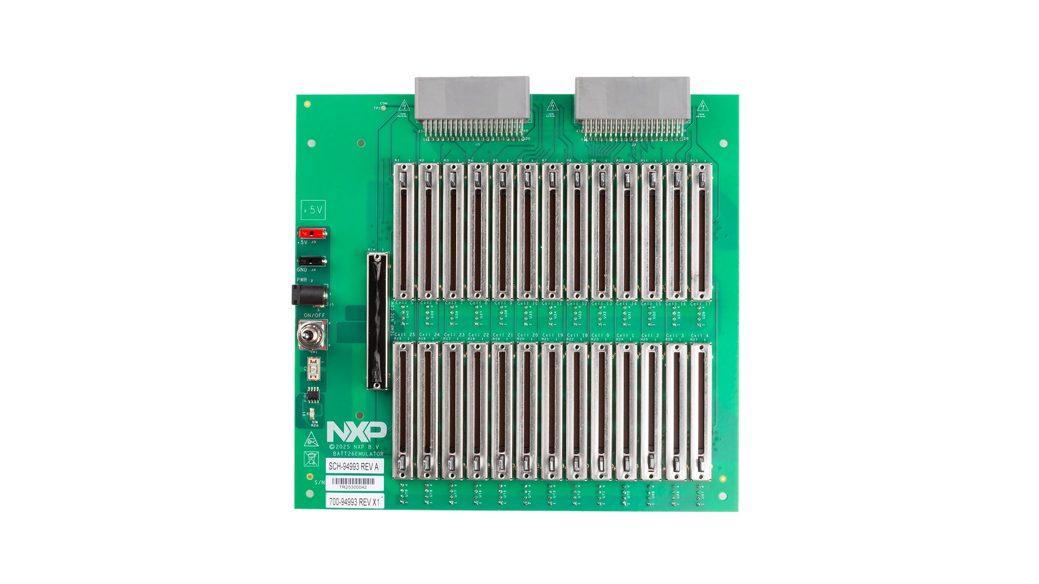
お客様の 26セル・バッテリー・パック・エミュレータ
1. パッケージの内容
NXPのアナログ製品開発ボードは、NXP製品の評価を目的とした使いやすいプラットフォームです。さまざまなアナログ・ソリューション、ミックスド・シグナル・ソリューション、パワー・ソリューションに対応しています。実績のある大容量テクノロジを使用したモノリシック集積回路 (IC) およびシステム・イン・パッケージ (SiP) デバイスを搭載しています。NXP製品は、最先端システムへの電源供給において、より長いバッテリー寿命、より小さいフォーム・ファクタ、より少ない部品数、より低いコスト、より優れたパフォーマンスを実現します。
このガイドでは、BATT26EMULATORボードをセットアップして使用する手順について説明します。
BATT26EMULATORボードは、BMA7126、BMA7426、BMA7124、BMA7424 26セルおよび24セル・バッテリー・セルコントローラ (BCC) の評価ボードに接続してマルチセル・バッテリー・パックをエミュレートできます
1.1 キットの内容
キットには以下のものが含まれています。
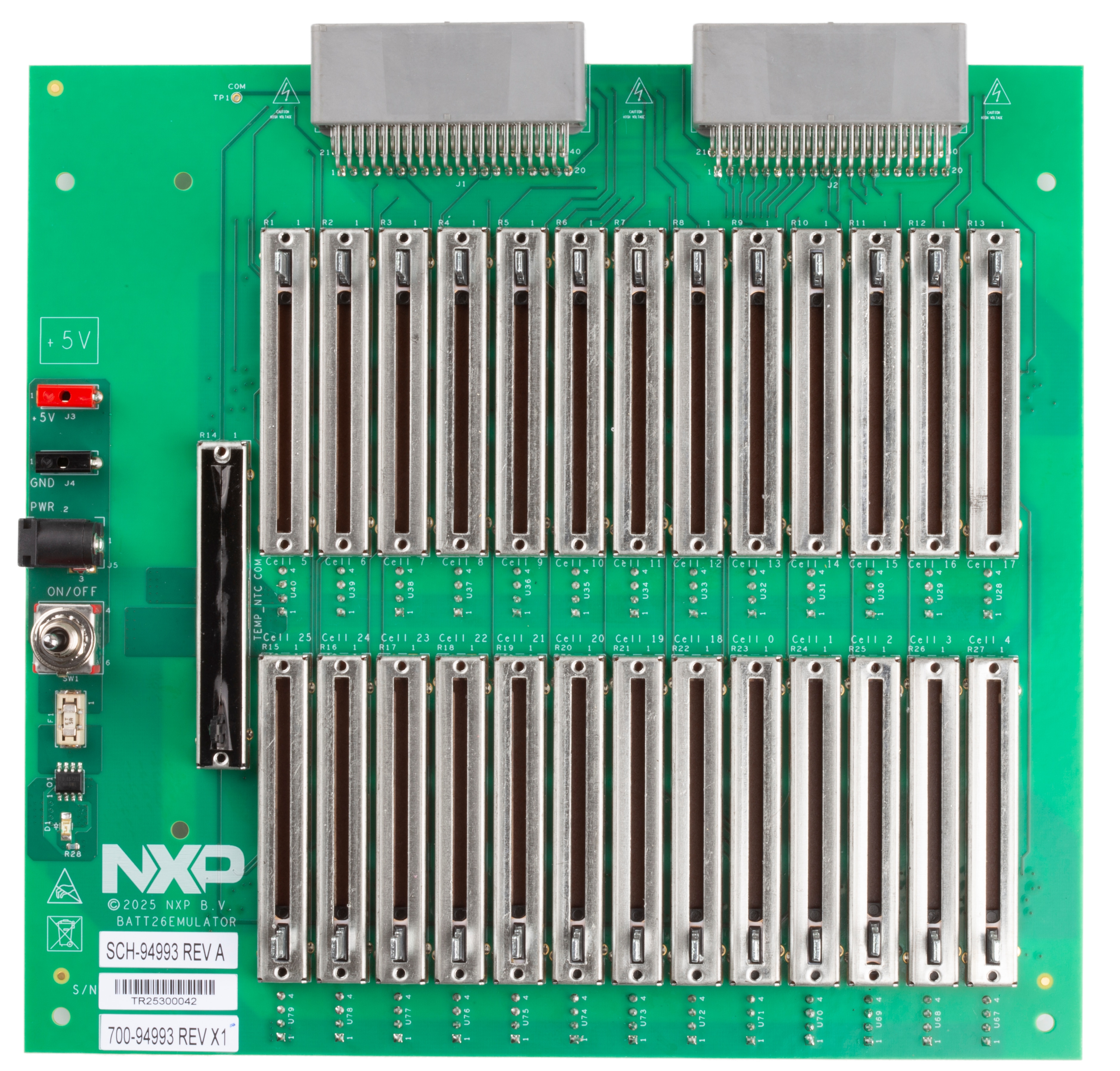
- BATT26EMULATOR、26セル・スライダ・バッテリー・パック・エミュレータ
- 25 W AC-DCアダプタ、+5 V DC/5 A単一出力、
P1JDCプラグ・タイプ (2.1 mm x 5.5 mm x 11 mm)、音叉型、センター・プラス - アダプタ・ケーブル、DCプラグ(2.1 mm x 5.5 mm x 11 mm~2.5 mm x 5.5 mm x 9.5 mm)
- プラスチック製保護カバー(別途取り付け)
ハードウェアの入手
2.1 ボードの特長
- 1.2 V~3.3 Vの範囲でセル電圧を調整するスライダ・ポテンショメータ x 26(合計スタック電圧は最大86 V)
- チャネルあたりの最大電流能力:200 mA
- EVBMA7X2YDT1評価ボード接続用のコネクタ x 2
- 温度センサの出力電圧を0 V~+4.95 Vの範囲で変化させ、NTC(負の温度係数)センサをシミュレートできます
2.2 ボードの説明
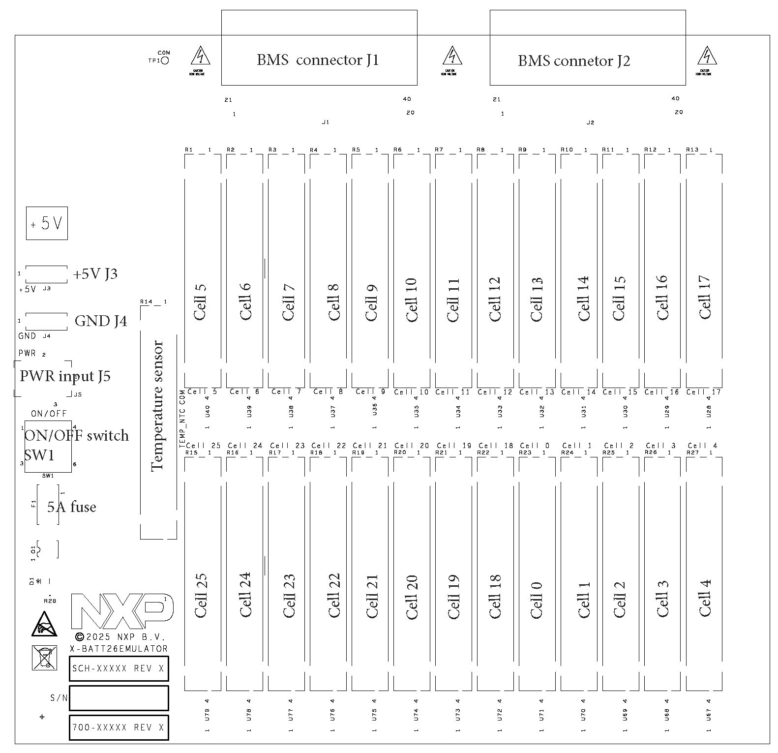
各セル・エミュレータは、安定化されていない絶縁型5 V-5 V DC-DCコンバータと調整可能なレギュレータで構成されています。セル電圧は、セル0~セル25の電圧スライダを使用して設定します。最小電圧は1.2 V、最大電圧は3.3 Vです。
2.3 接続と設定
このエミュレータ・ボードには、電流能力が5 Aの5V DC電源が必要です。電源は、J5(Ø2.5 mmジャック・コネクタ)または2 mmのバナナ端子J3(+) およびJ4(-) を介してボードに接続します。センター・ピンが正電圧に、リング端子がグランドに接続されます。ボードの入力は5 Aヒューズで保護されています。LEDは、ボードの電源が入っていることを示します。ジャック・コネクタに電圧が印加されているにもかかわらずLEDが点灯しない場合は、F1ヒューズを確認してください。
「EVBMA7X2YDT1」評価ボードは、コネクタJ1とJ2に最大2つ接続できます(接続は順不同)。
2.4 コネクタ
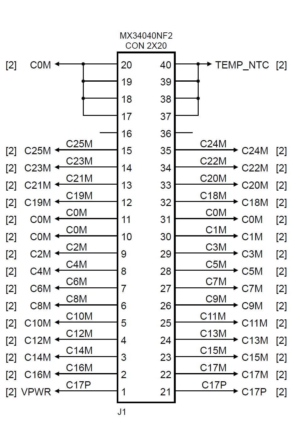
図3に示すように、2つの40ピンコネクタJ1およびJ2 (JAE Electronics MX34040NF2) は並列に接続されています。これらのコネクタには、最大2つのボード(EVBMA7X2YDT1など)を接続できます。
BATT26EMULATORは、EVBMA7X2YDT1と組み合わせて使用することを目的として設計されています。BMA7x2y BCC ICのアーキテクチャに準拠するために、18個のセルがBCCグランド (GND) の上に配置され(セル0~17のスライダ)、8個のセルがBCC GNDの下に配置されています(セル18~25のスライダ)。GNDはC0Mに接続されています。
セル0のスライダはC0M (cell0M) とC1M (cell0P) 間の電圧を設定し、セル1のスライダはC1M (cell1M) とC2M (cell1P) 間の電圧を設定します。以降も同様です。セル17のスライダはC17M (cell17M) とC17P (cell17P) 間の電圧を設定します。
C17P-PWR(ピン1)およびGND(ピン17~20)は、BMA7X2YDT1への給電に使用され、評価ボードの消費電流に伴う電圧降下を避けるために、それぞれC17PおよびC0Mから分離されています。
温度センサ・スライダは、ピン37~ピン40に接続されています。