Getting Started with the TEA6017DK1005 Evaluation Board
このドキュメントの内容
-
Out of the Box
-
Get to Know the Hardware
-
Configure Hardware
サインイン 進行状況を保存するには アカウントをお持ちでない方 アカウントを作成する。
お客様の TEA6017AT Programming Board and Development Samples
1. Out of the Box
The NXP analog product development boards provide an easy-to-use platform for evaluating NXP products. The boards support a range of analog, mixed-signal and power solutions. They incorporate monolithic integrated circuits and system-in-package devices that use proven high-volume technology. NXP products offer longer battery life, a smaller form factor, reduced component counts, lower cost and improved performance in powering state-of-the-art systems.
This page will guide you through the process of setting up and using the TEA6017DK1005 programming board.
1.1 Kit Contents and Packing List
The contents of the TEA6017DK1005 kit are:
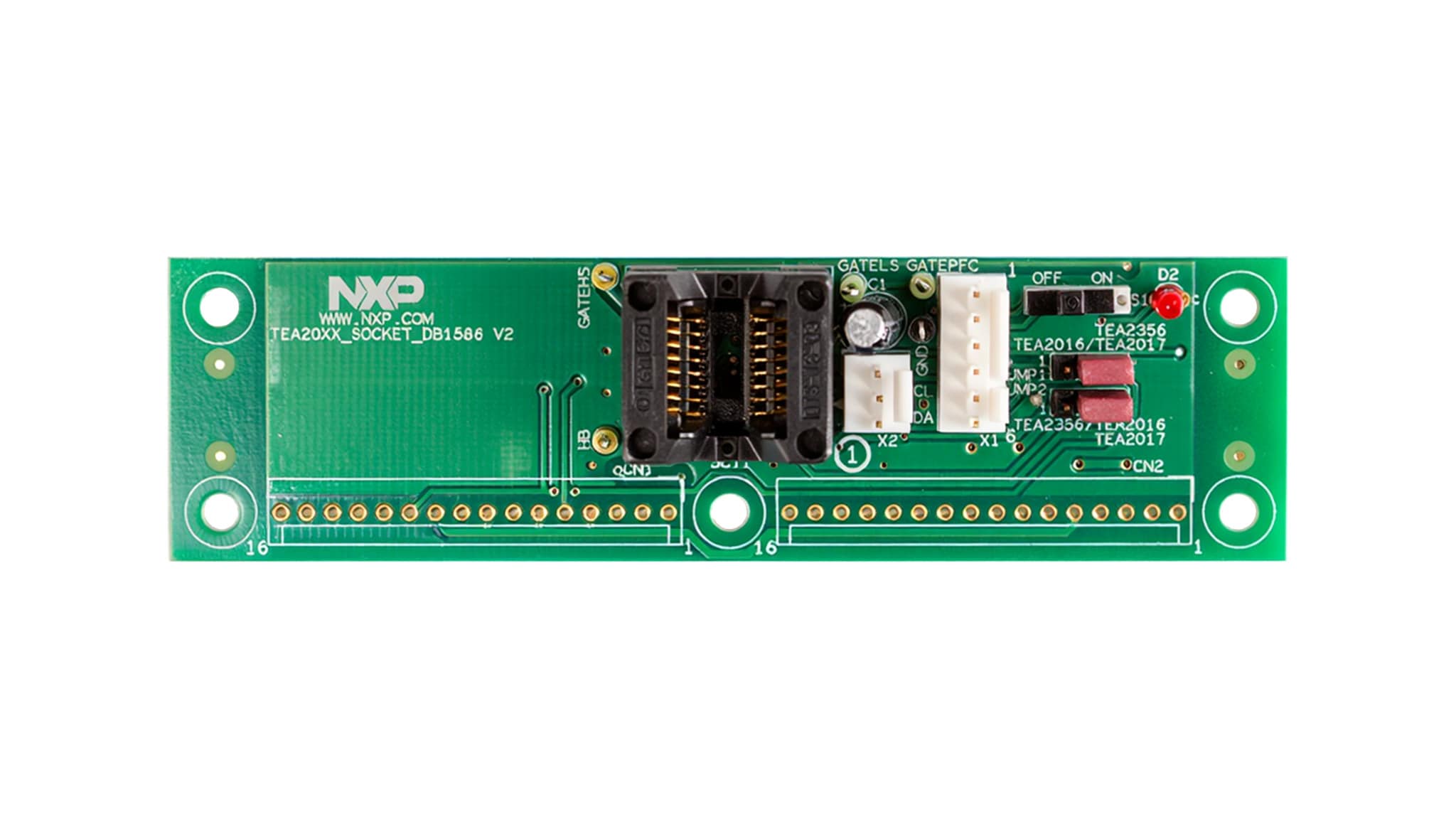
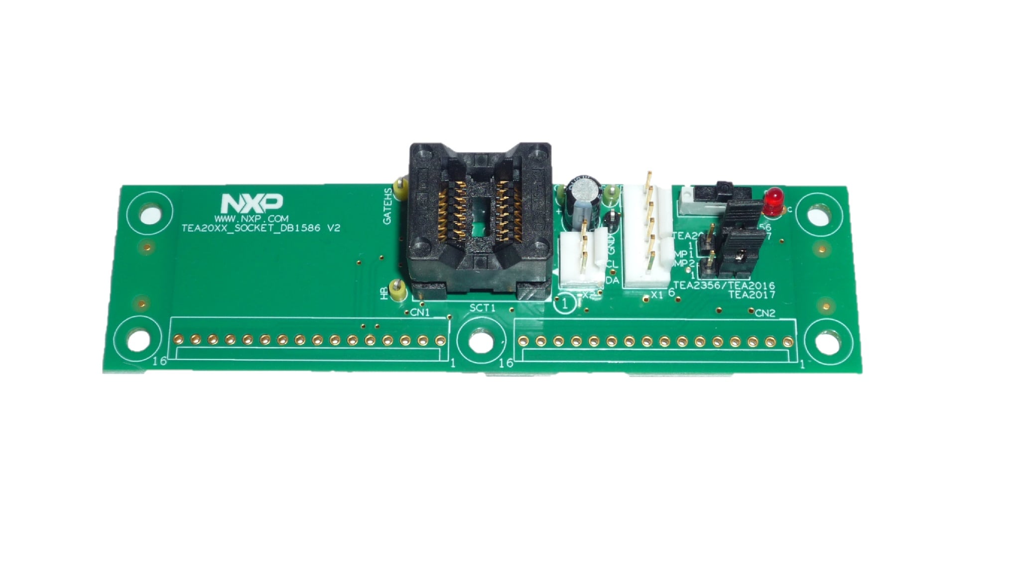
- TEA20xx_SOCKET_DB1586 programming board
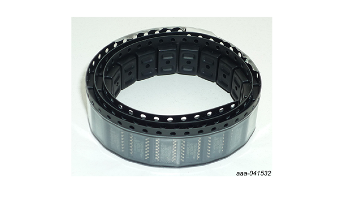
- 20 IC’s TEA6017ATdev
1.2 Additional Hardware
In addition to the kit contents, the following hardware is necessary or beneficial when working with this kit.
2. Get to Know the Hardware
2.1 Board Features
This board can be used for programming small series of TEA6017, TEA2017 or TEA2016 samples. Place the jumper on the board in the TEA2017 position when programming TEA6017 samples. By connecting both the 3pin and 6pin connector to the USB-I²C programming interface, regular production samples and development samples can be programmed after selecting the correct channel with the switch on the USB-I²C interface.
2.2 Board Description
The TEA6017AT digital architecture is based on a high-speed configurable hardware state machine ensuring very reliable real-time performance.
Several parameters can easily be configured during evaluation with use of the graphical user interface (GUI):
- Operating frequencies to be outside the audible area at all operating modes
- Soft start and soft stop in burst mode, reducing the audible noise
- Accurate transition levels between operation modes (high-power mode/low-power mode/burst mode)
- Enabling/disabling the lower power mode
TEA6017AT samples can be easily programmed using the TEA20xx_SOCKET_DB1586 board in connection with the TEA2016DB1514v2 demo kit and the GUI.
3. Configure Hardware
3.1 Configure the Hardware
Both TEA6017AT and TEA6017ATdev samples can be programmed by means of the TEA20xx_Socket_DB1586 board + I²C interface (RDK01DB1563). The jumper on the TEA20xx_Socket_DB1586 board must be set in the TEA2017 position when programming TEA6017AT or TEA6017ATdev samples. The selector switch on the I²C interface must be set in the position that depends on whether TEA6017AT or TEA6017ATdev samples are being programmed.
Design Resources
Support
Forums
Connect with other engineers and get expert advice on designing with the TEA6017DK1005 on one of our community sites.