Getting Started with the S32K344EVB-LQ100 Evaluation Board
このドキュメントの内容
-
Out of the Box
-
Get Software
-
Plug It In
-
Create Application Project
-
Build and Run
サインイン 進行状況を保存するには アカウントをお持ちでない方 アカウントを作成する。
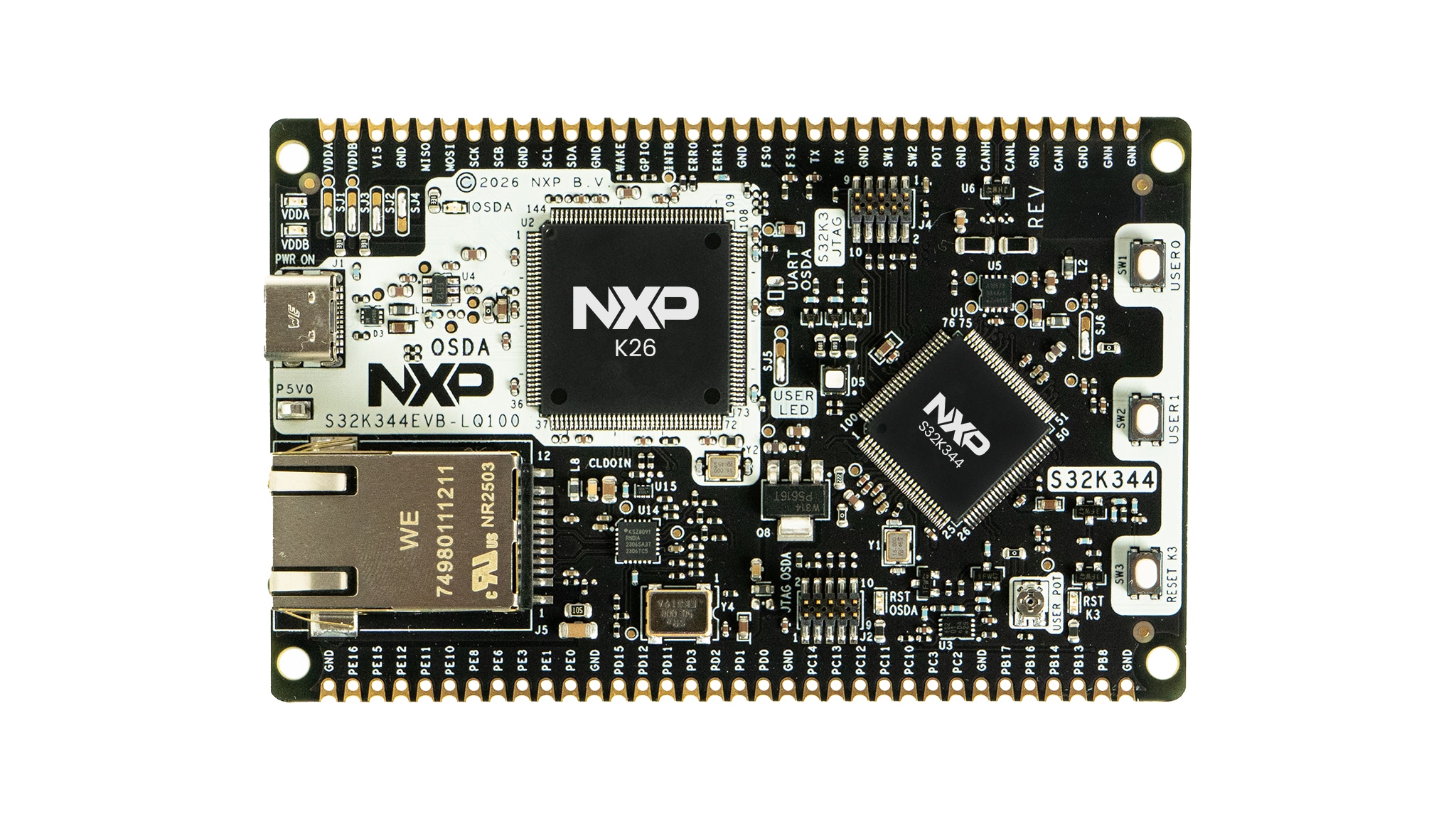
お客様の S32K344EVB-100LQ 車載向け汎用評価ボード
1. Out of the Box
The S32K344EVB-LQ100 is an evaluation board (EVB) based on the NXP S32K344 automotive microcontroller (MCU). The device features dual Arm® Cortex®-M7 cores, functional safety support up to ASIL-D, an integrated hardware security engine (HSE), advanced communication peripherals, floating-point support and low-power operating modes, making it suitable for automotive and industrial applications.
This guide will walk you through setting up the S32K344EVB-LQ100, preparing the required development tools as well as creating, configuring, building and running an application in S32 Design Studio (S32DS).
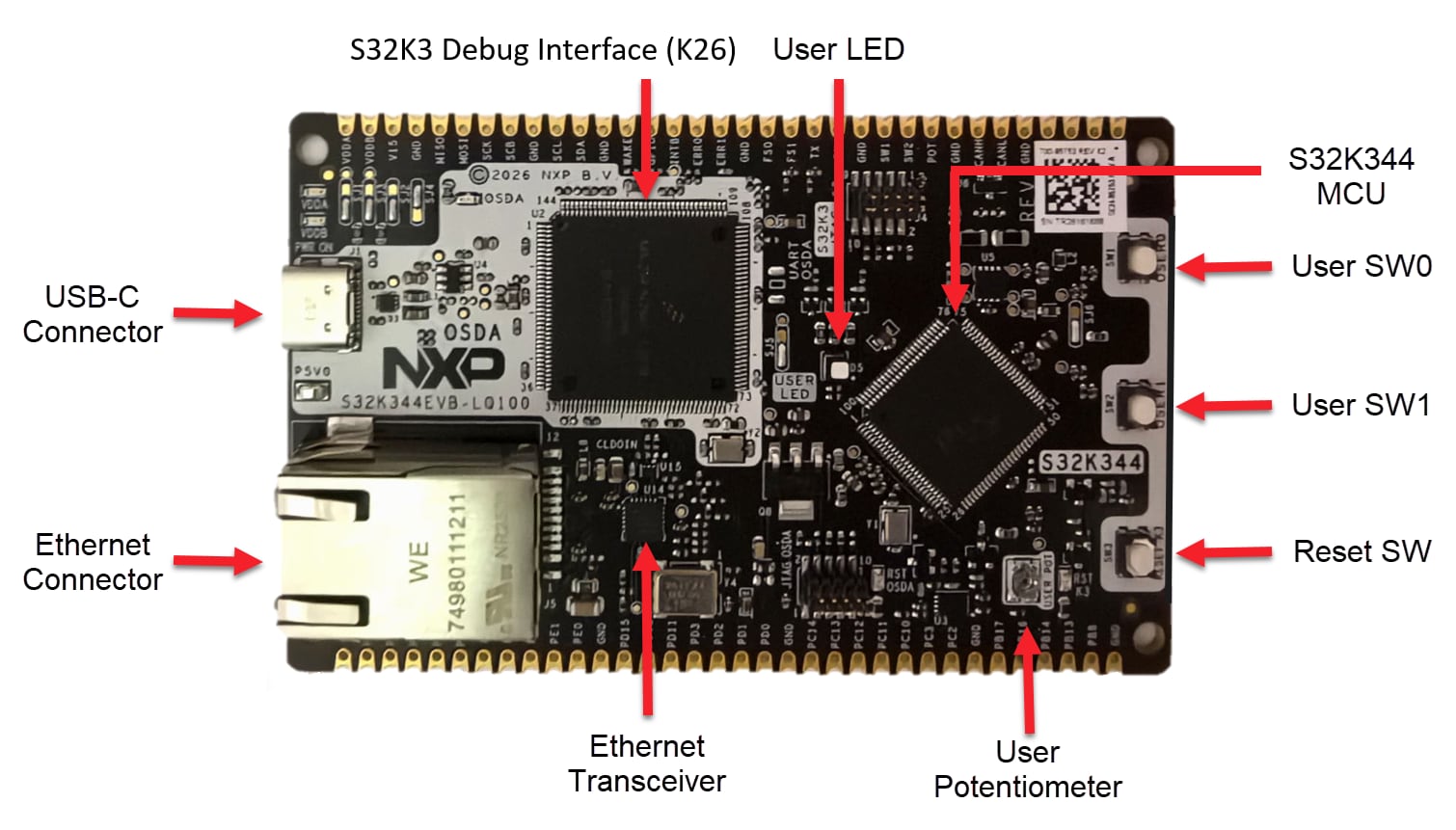
1.1 Get to Know the S32K344EVB-LQ100 Evaluation Board
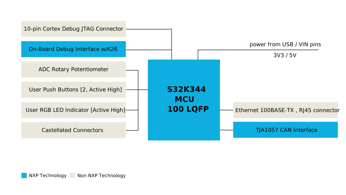
To help familiarize you with the board, the figure below labels the EVB's core components.
2. Get Software
To obtain the software needed to set up and use the evaluation board, you will first need to log in to NXP.com with your credentials.
2.1 Select Software Packages from Automotive Software Package Manager
In this step, you will locate the software needed for the S32K344EVB-LQ100. Go to the Automotive Software Package Manager and select "S32K3" as your device under "General Purpose MCUs."
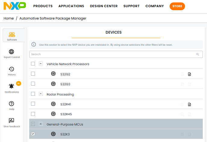
To locate the software downloads required for this EVB, expand the menu hierarchy and navigate to the "FRDM Automotive S32K3 + S32M27 Board Installation Package" bundle. From the available components, select at least "S32 Design Studio and Configuration Tools" and "Real-Time Drivers." All other software packages in this category are optional and may be installed as needed.
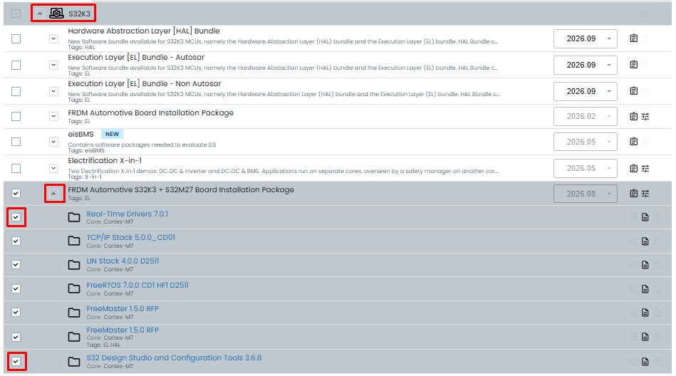
Once you have selected the software components, you will click the button labeled "GENERATE BUNDLE INSTALLER" located below the drop-down menu.

Before you can use the software, you will be required to review the Export Control information and the Software License Agreement. Follow the wizard to complete the following steps:
- Review the Export Control information.
- Review the entire Software License Agreement by scrolling to the bottom, then accept the agreement
- Close the wizard window after completing the required prompts. Installer and Installer User Manual download will start automatically in a few moments
Note: Because the NXP Multi Installer is only active for a limited time after it is generated, it is recommended that you begin the installation as soon as the download is complete.
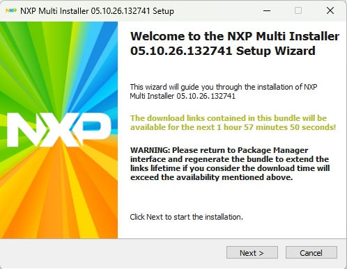
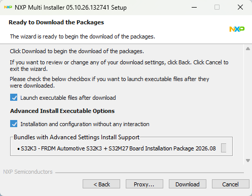
The FRDM Automotive Board Installation Package automatically installs and configures the required software, simplifying the setup process.
2.2 Add GCC Toolchain Version 10.2
The latest version of S32 Design Studio includes the GNU Compiler Collection (GCC) v11.4 toolchain. To ensure full compatibility between the toolchain and the Real-Time Drivers (RTD), you will also need to install GCC v10.2.
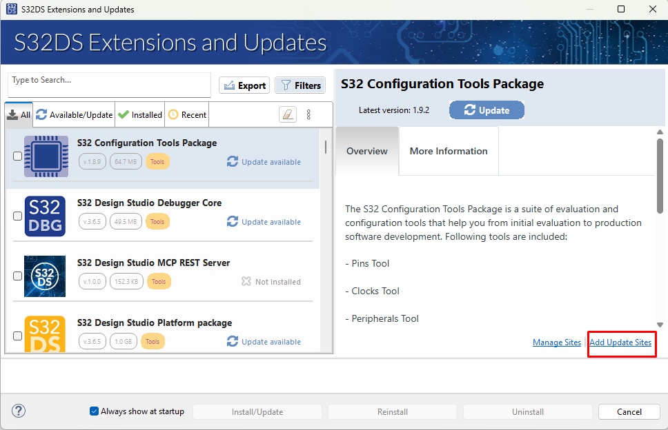
To install the GCC v10.2 toolchain, select Help → S32DS Extensions and Updates from the S32 Design Studio top menu. In the S32DS Extensions and Updates dialog, locate and install GCC v10.2.
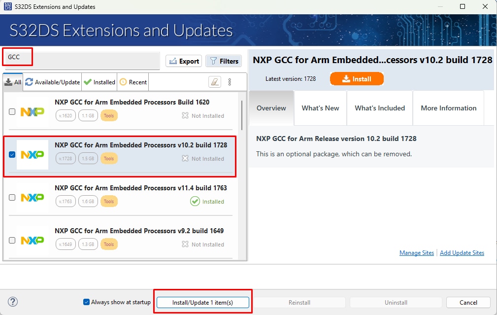
Note: Optional software is also available for download from the S32K3 Standard Software Package or S32K3 Reference Software Package. In S32DS, go to Help → S32DS Extensions and Updates from the top menu to open the S32DS Extensions and Updates dialogue where you click on Add Update Sites link. Or use drag and drop option - just drag downloaded updatesite file and drop on S32DS Extensions and Updates menu. Added sw package will be also automatically selected for following installation. Refer to the screenshots above and below for examples.
3. Plug It In
In this step, to prepare the board for use you will connect the S32K344EVB-LQ100 evaluation board to your computer and power it on.
3.1 Check the Default Solder Jumper Positions in the S32K344EVB-LQ100 EVB
Refer to both the board layout image and the table below to locate the jumpers.
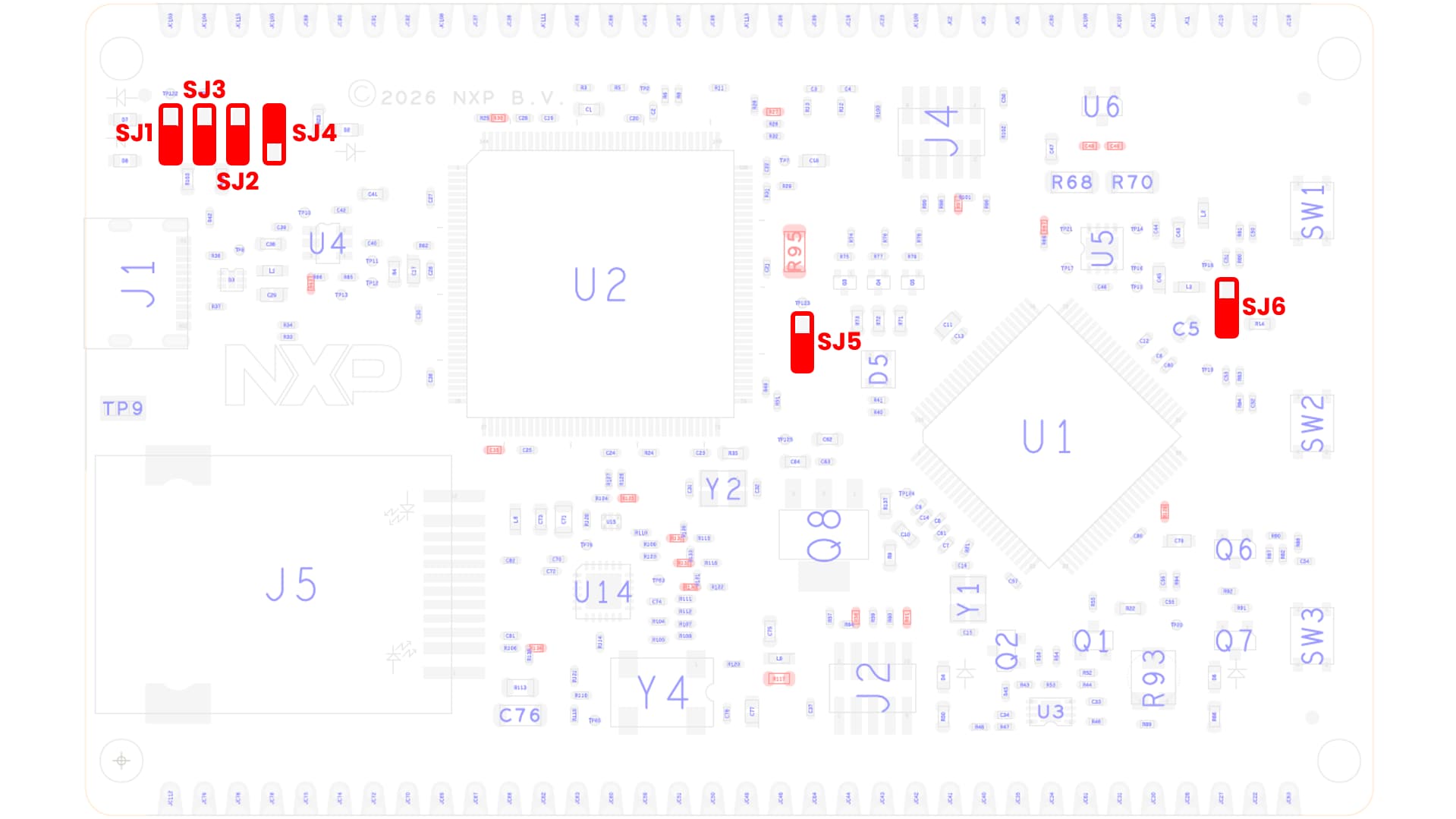
| Jumper | State | Notes |
|---|---|---|
SJ1 |
1-2 | VDD_HV_A domain powered from USB |
SJ2 |
1-2 | VDD_HV_A domain voltage 5 V |
SJ3 |
1-2 | VDD_HV_B domain powered from USB |
SJ4 |
1-2 | VDD_HV_B domain voltage 3.3 V |
SJ5 |
1-2 | V15_MCU domain powered via external NPN ballast transistor from VDD_HV_B domain |
SJ6 |
1-2 | TJA1057 CAN Transceiver powered from VDD_HV_A domain |
3.2 Plug In the Power Supply and S32K3 Debug Interface
Next, you will power the board by connecting a USB Type-C to the J1 connector.
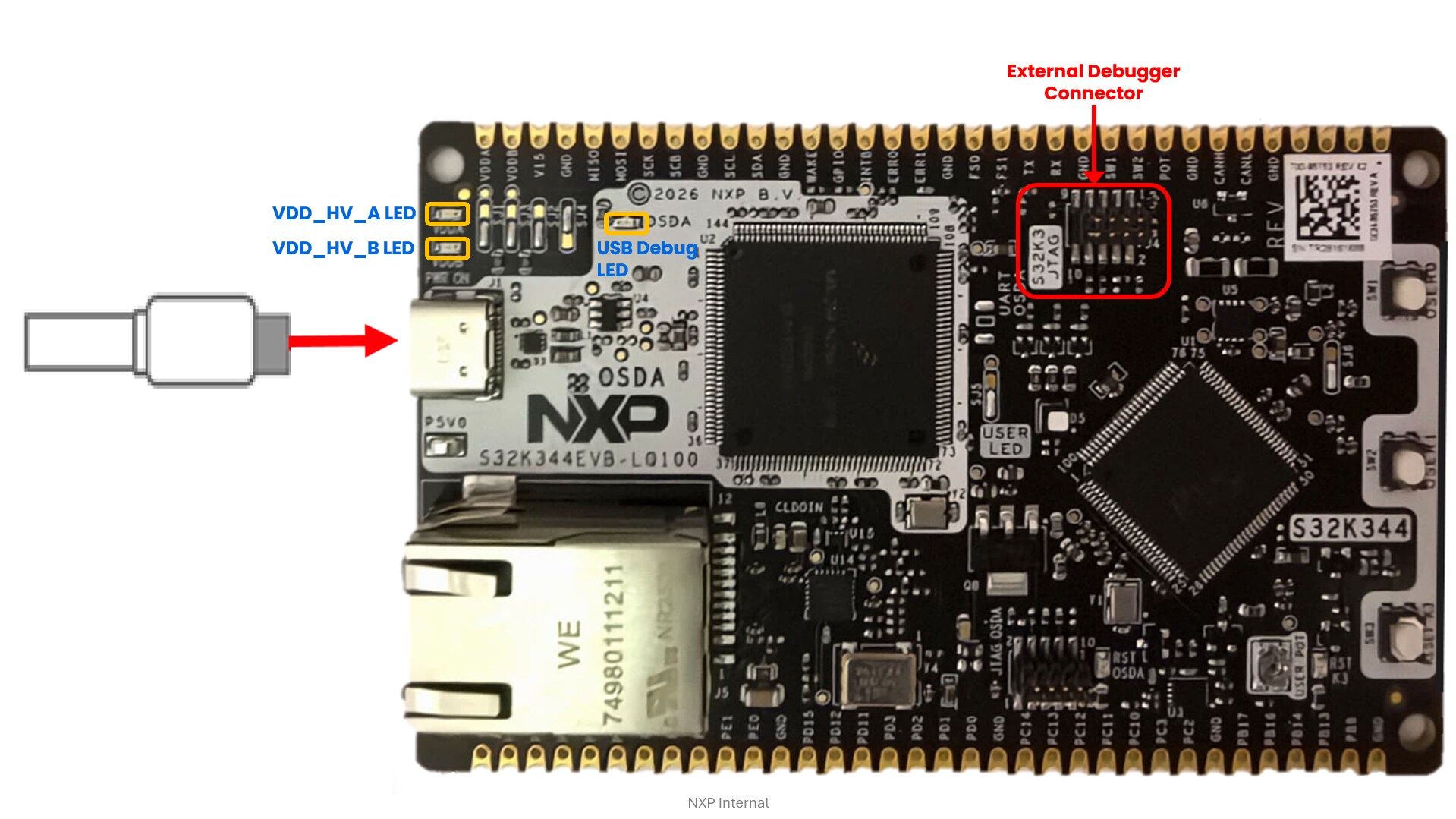
Three orange LEDs indicates the presence of the VDD_HV_A and VDD_HV_B supply voltages, and that the S32K3 debug interface is ready.
You also have the option to program the S32K3 MCU using the 10-pin Arm Cortex Debug Connector. To use this option,
connect an external debug interface to connector J4, located above the S32K3 MCU.
4. Create Application Project
In this step, you will use S32DS to create and configure an application project for the S32K344EVB-LQ100 EVB.
4.1 Create New S32DS Project
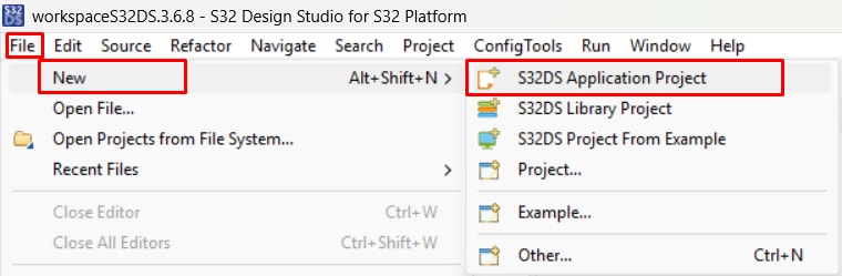
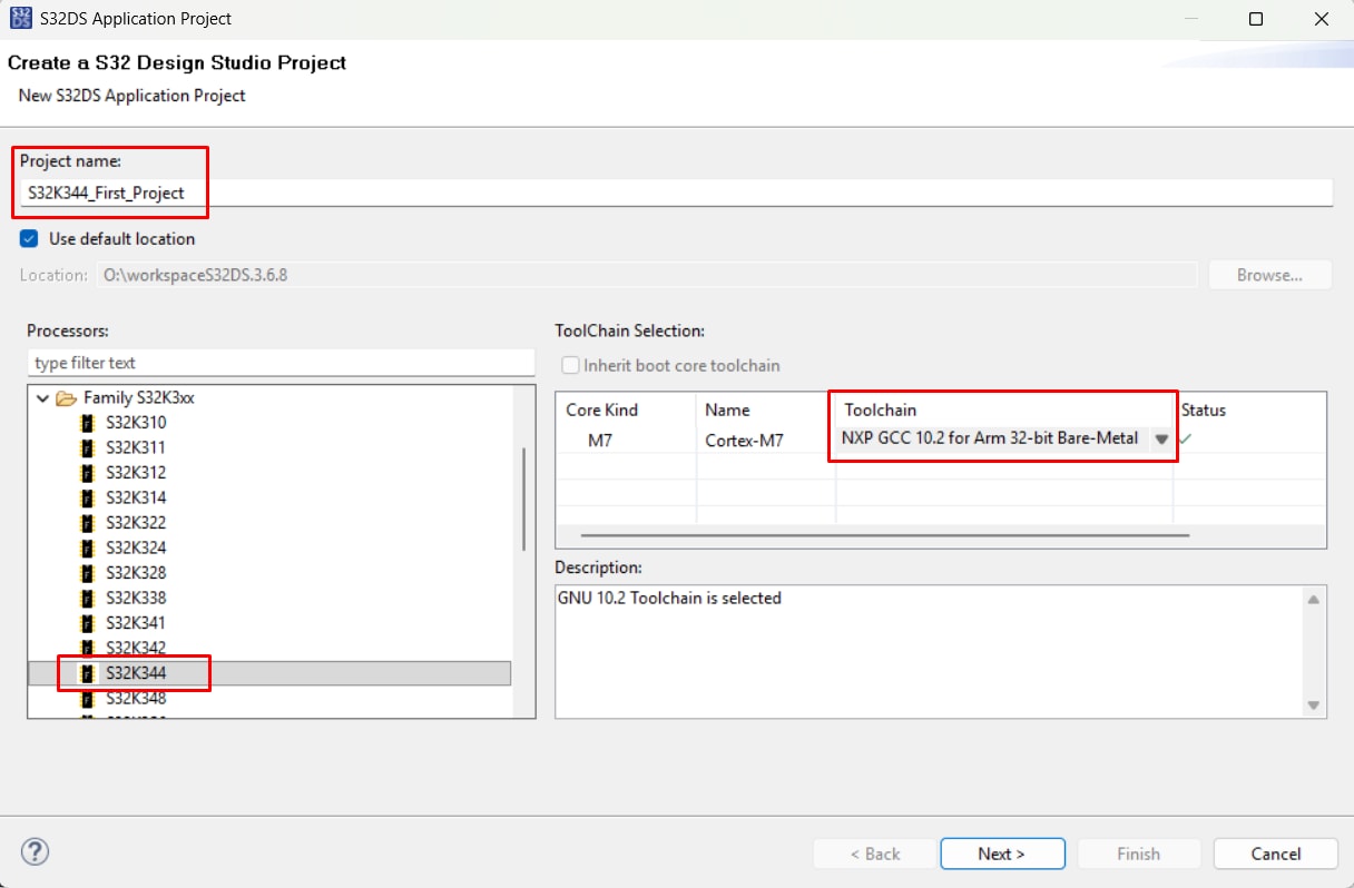
- Open S32 Design Studio. From the top menu, select File → New → S32DS Application Project
- Enter a project name (without spaces), select the S32K344 derivative and select GCC 10.2 as the toolchain
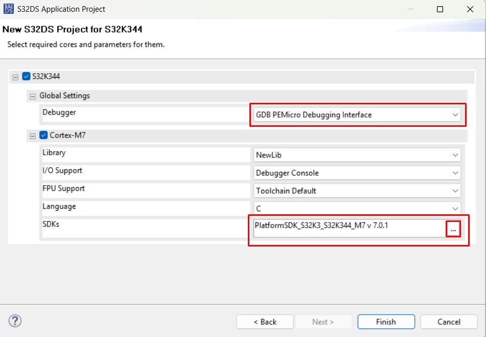
- Select Debugger and RTD Drivers as the Platform SDK, then select Finish to create the project
4.2 Configure Pins
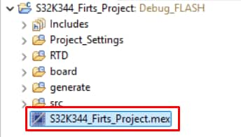
- Expand the project file folder, then double-click the .mex file to open the project configuration in the Configuration Tool
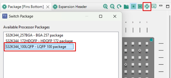
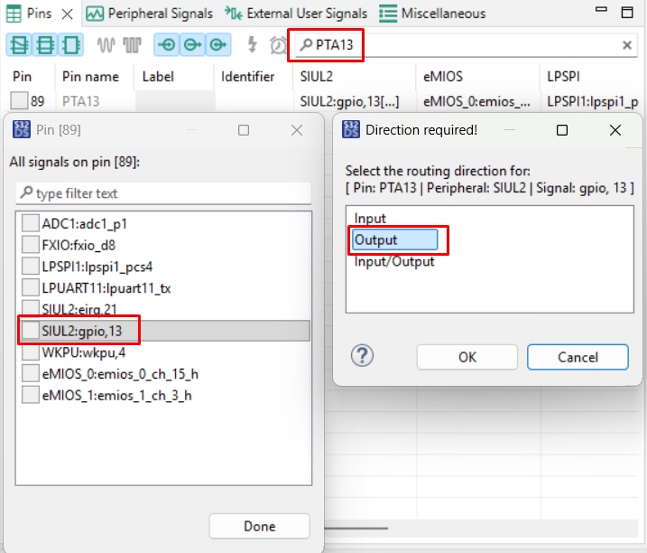
- Select the LQFP 100 package
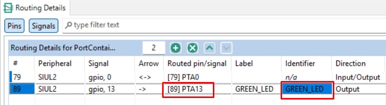
- Configure the
PTA13pin, which is connected to the green LED, as a GPIO output - Enter an identifier for
PTA13(without spaces), such asGREEN_LED
Note: PTA14 = Blue LED; PTE2 = Red LED
4.3 Add Driver and Generate Configuration Files
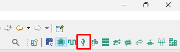
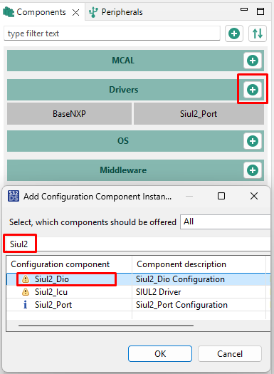
- Switch to the "Peripherals" perspective, then add the
Siul2_Diodriver to the application - Verify that the correct project is selected, then click on "Update Code" to generate the configuration files

4.4 Edit Code
- Revert to the C/C++ perspective
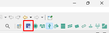
- Edit main.c file in src folder, including the Port and Dio drivers
- Enter the command line for pin initialization
- Finally, add the command to toggle the
GREEN_LEDpin
/* Including necessary configuration files. */

    #include "Mcal.h"

    #include "Siul2_Port_Ip.h"
    #include "Siul2_Dio_Ip.h"

    volatile int exit_code = 0;

/* User includes */int main(void)
{
/* Write your code here */
Siul2_Port_Ip_Init(NUM_OF_CONFIGURED_PINS_PortContainer_0_BOARD_InitPeripherals,g_pin_mux_InitConfigArr_PortContainer_0_BOARD_InitPeripherals);
for(;;)
{
}
return exit_code;
}Note: While editing the code, you may use shortcuts: Pressing CTRL + Space generates a list of the available functions or arguments. Also, remember to include a semicolon at the end of your line of code.
int main(void)
    {
    /* Write your code here */

    Siul2_Port_Ip_Init(NUM_OF_CONFIGURED_PINS_PortContainer_0_BOARD_InitPeripherals,g_pin_mux_InitConfigArr_PortContainer_0_BOARD_InitPeripherals);
    for(;;)
    {

    Siul2_Dio_Ip_TogglePins(GREEN_LED_PORT, 1<<(GREEN_LED_PIN));

} return exit_code; }5. Build and Run Application Project
Now, you will take your S32K344EVB-LQ100 EVB for a test drive. Follow the instructions in each subsection to build the application, upload it to the S32K344 and also debug the code in S32 Design Studio.
5.1 Build and Upload Software
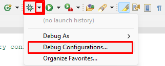
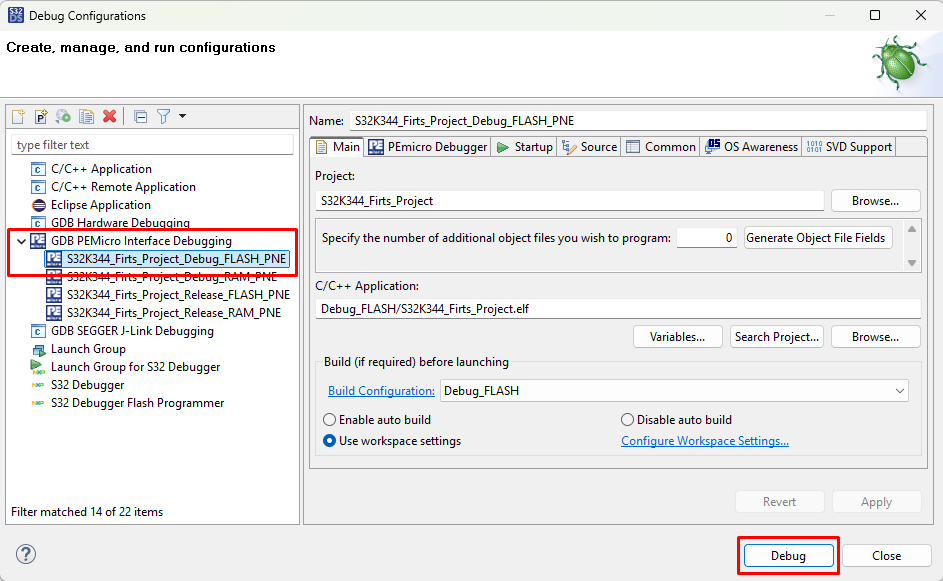
Open the Debug Configurations menu, then select one of the predefined debug configurations to build the application and upload it to the S32K344 microcontroller (MCU).
5.2 Debug Code
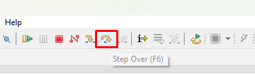
S32 Design Studio switches to the Debug perspective. Select Step Over or press F6 to step through the code.
The green LED should now be toggling in a continuous loop.
5.3 Add Clock Initialization Code (Optional)
Similar to the "Edit Code" step in the previous section, you may update the code for clock initialization.
/* Including necessary configuration files. */
#include "Mcal.h"

#include "Siul2_Port_Ip.h"
#include "Siul2_Dio_Ip.h"

#include "Clock_Ip.h"

volatile int exit_code = 0;
/* User includes */
int main(void)
{

    Clock_Ip_StatusType ClockStatus;
    ClockStatus = Clock_Ip_Init(&Clock_Ip_aClockConfig[0]);

    /* Write your code here */
    Siul2_Port_Ip_Init(NUM_OF_CONFIGURED_PINS_PortContainer_0_BOARD_InitPeripherals,
    g_pin_mux_InitConfigArr_PortContainer_0_BOARD_InitPeripherals);

    for(;;)
    {
        Siul2_Dio_Ip_TogglePins(GREEN_LED_PORT, 1<<(GREEN_LED_PIN));
    }
    return exit_code;
}Design Resources
The resources listed below have been curated to support you through the evaluation and development process.
Board Information
Chip Documents
Software
-
Automotive Software Package Manager
-
S32K3 Standard Software Package
-
S32K3 Reference Software Package
- S32 Design Studio IDE
- Real-Time Drivers (RTD)
- S32K Power Estimation Tool (PET)
- Model-Based Design Toolbox (MBDT)
- Structural Core Self-Test (SCST) Library
- FreeMASTER Run-Time Debugging Tool
- Inter-Platform Communication Framework (IPCF)
- Automotive Math and Motor Control Library (AMMCLib)
- S32 Safety Software Framework (SAF) and Safety Peripheral Drivers (SPD)
このページ
- 2.1
Select Software Packages from Automotive Software Package Manager
- 2.2
Add GCC Toolchain Version 10.2
- 3.1
Check the Default Solder Jumper Positions in the S32K344EVB-LQ100 EVB
- 3.2
Plug In the Power Supply and S32K3 Debug Interface