KITPF8150FRDMEVMおよびKITPF8250FRDMEVM評価ボードのスタート・ガイド
サインイン 進行状況を保存するには アカウントをお持ちでない方 アカウントを作成する。
お客様の KITPF8X50FRDMEVM
1. パッケージの内容
KITPF8150FRDMEVM/KITPF8250FRDMEVMは、NXP製品を迅速に評価するために必要なすべてのヘッダ、ジャンパ、および信号テスト・ポイントで構成された評価ボードです。
このドキュメントは、ユーザーがKITPF8150FRDMEVM/KITPF8250FRDMEVM評価ボードをすぐにセットアップ、構成、および操作できるようにすることを目的としています。
1.1 キットの内容と同梱物一覧
KITPF8150FRDMEVMまたはKITPF8250FRDMEVMを使用するには、キットの同梱物と追加のハードウェアに加え、ソフトウェアがインストールされたWindows PCワークステーションが必要です。
- 組立ておよびテスト済み評価ボードとプログラム済みFRDM-KL25Zマイクロコントローラ・ボード(静電気防止バッグ入り)
- 3.0フィートのUSB-STD A to USB-B-miniケーブルまたはUSB-Type Cケーブル(FRDM-KL25Zボードのバージョンによって異なります)
- クイック・スタート・ガイド
1.2 追加ハードウェア
このボードの作業をする際は、キットの内容物のほかに以下のハードウェアが必要であり、またこれを使用すると役立ちます。
- 電圧範囲3.0~5.0 V、電流制限初期値1.0 A(最大消費電流7.0 A)の電源
1.3 Windows PCワークステーション
この評価ボードにはWindows PCワークステーションが必要です。この評価ボードで作業する際は、これらの最低限の仕様を満たすことで良好な結果が得られます。
- Windows 7~11を搭載したUSB対応のコンピュータ
1.4 ソフトウェア
この評価ボードで作業するには、ソフトウェアのインストールが必要です。NXPの車載用PMIC製品では、1種類のユニバーサルGUIが提供されています。これは、NXPの車載PMICファミリ向けGUIのリンクから入手できます。
最新バージョンのGUIをダウンロードし、PCにインストールしてください。GUIを使用することで、評価ボード (EVB) の操作が簡単になります。このドキュメントでは、Rev 10.0.0を使用して例を示します。GUIフォルダには、1つのバージョンのPF8xファームウェアが提供されています。FRDM-KL25Z補助ボードを使用するには、このバージョンのアップデートが必要な場合があります。
1.5 ユーザー・マニュアル
評価ボードのすべての機能については、UM12404、KITPF8150FRDMEVM/KITPF8250FRDMEVM評価ボードのユーザー・マニュアルを参照してください。
2. ハードウェアについて
2.1 ボードの概要
KITPF8150FRDMEVMまたはKITPF8250FRDMEVMは、NXP製品を評価するための使いやすいプラットフォームを提供します。さまざまなアナログ・ソリューション、ミックスド・シグナル・ソリューション、パワー・ソリューションに対応しています。実績のある大容量テクノロジを使用したモノリシック集積回路およびシステム・イン・パッケージ (SiP) デバイスを搭載しています。NXP製品は、最先端システムへの電源供給において、より長いバッテリー寿命、より小さいフォーム・ファクタ、より少ない部品数、より低いコスト、より優れたパフォーマンスを実現します。
これらのカスタマー評価ボードは、PF8150/PF8250パワー・マネジメントICを搭載しています。キットは、PMICを完全に評価するために必要なすべてのハードウェアを統合しています。GUIソフトウェアとのインターフェースとしてFRDM-KL25Z開発ボードに基づく通信ブリッジを搭載し、これによりPF8150/PF8250 PMICを完全に設定および制御できます。
2.2 ボードの特長
降圧レギュレータ
SW1、SW2、SW3、SW4、SW5、SW6:0.4 V~1.8 V、2500 mA、精度1.5%、ダイナミック電圧スケーリング、単相/2相/3相/4相構成SW7:1.0 V~4.1 V、2500 mA、精度2%- 設定可能なVTT終端モードをSW6に搭載
- プログラム可能な電流制限
- スイッチング周波数のスペクトラム拡散と手動調整
LDOレギュレータ
- 4個のLDOレギュレータ: 1.5 V~5.0 V、400 mA、精度3%、オプションのロードスイッチ・モード
- LDO2でハードウェア/ソフトウェア制御を選択可能
RTC電源
- VSNVS:1.8 V/3.0 V/3.3 V、10 mA
- 充電電流および電圧をプログラム可能なコイン電池充電機能を搭載したバッテリー・バックアップ式メモリ
システムの特長
- 2.7 V~5.5 Vの動作入力電圧範囲
- FRDM-KL25Zインターフェースを介したUSB-I²C通信
- デフォルトのハードワイヤPMIC設定またはOTP/TBB動作を選択可能
- 400 kHzで動作するファストモードI²C通信(PMICによる高速動作をサポート)
- PMICおよびシステムのアナログ・マルチプレクサ (AMUX) による高度なシステム監視/診断
- プライマリ/セカンダリ・インターフェース・コネクタ
- 1.8 V/3.3 Vの出力電圧を選択可能なオンボードI/Oレギュレータ
2.3 ボードの説明
KITPF8150FRDMEVM/KITPF8250FRDMEVMは、PF8150/PF8250の完全な評価を可能にするハードウェア評価ボードです。PF8150/PF8250デバイス・ファミリは、NXPのi.MX 8プロセッサおよびS32xプロセッサ、ならびにNXP製以外のその他のプロセッサをベースとした高性能アプリケーション向けに設計されたパワー・マネジメント集積回路 (PMIC) です。7つの高効率降圧コンバータと4つのリニア・レギュレータを備え、プロセッサやメモリなどのペリフェラルに電力を供給します。
内蔵のワンタイム・プログラマブル・メモリに主要な起動設定を保存することで、出力電圧と外部レギュレータのシーケンスを設定するために通常使用される外付けコンポーネントを大幅に削減できます。レギュレータのパラメータは、起動後に高速I²Cを介して調整可能であり、さまざまなシステム状態に柔軟に対応できます。
PF8150/PF8250ファミリは、市場のさまざまなニーズに対応するために、以下の2つのバージョンのPMICで構成されています。
- PF8250は、このファミリのフラグシップ・バージョンで、ISO 26262規格に準拠した機能安全メカニズムを備えたフル機能のPMICであり、ASIL B/D車載モジュール向けの強力で柔軟なソリューションを提供します
- PF8150は、この製品のセーフティ非対応バージョンであり、PF8250と同じパワー・マネジメント機能およびデジタル制御機能を備えていますが、機能安全のオーバーヘッドがないため、非セーフティ関連システム向けにより経済的なプラットフォームを提供します
主な特長を表1に示します。
| デバイス | 説明 | 特長 |
|---|---|---|
| PF8150 | 高性能プロセッシング・アプリケーション向けパワー・マネジメント集積回路 (PMIC) |
|
| PF8250 | 高性能プロセッシング・アプリケーション向けPMIC |
|
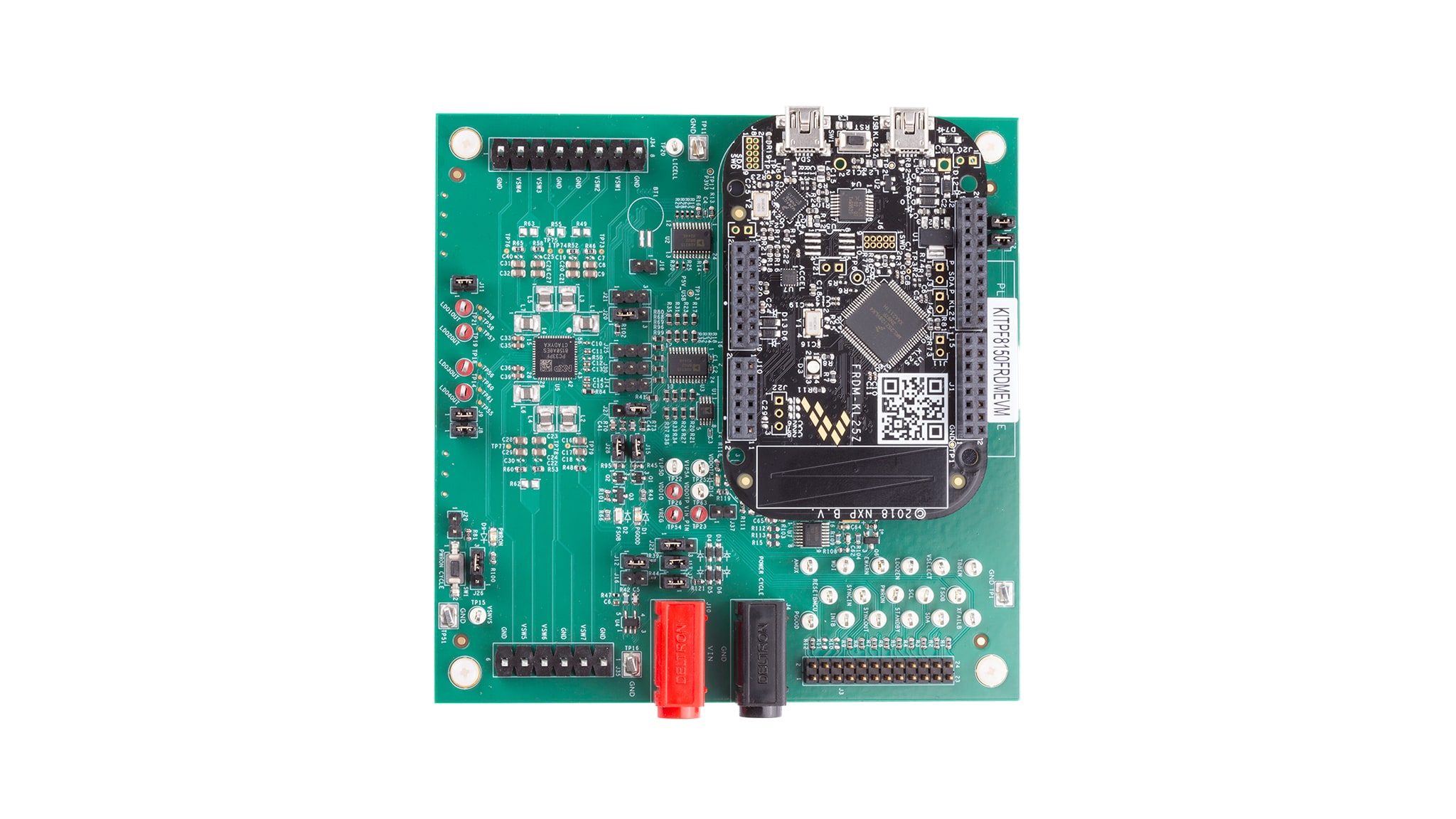
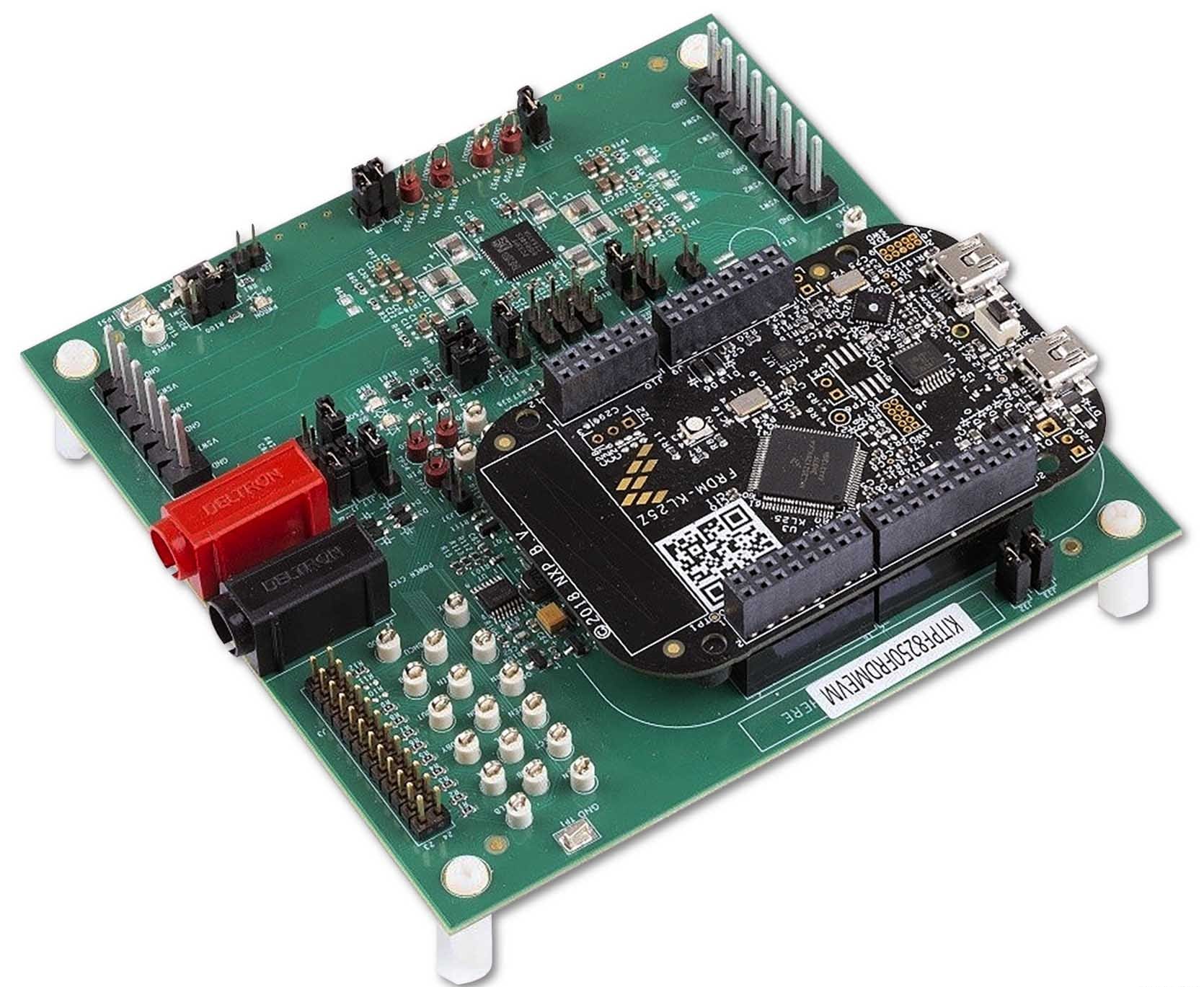
この製品は、以下の最終組み立て図(図1)に示すように、FRDM-LKL25を搭載したマルチボード構成となっています。
3. ハードウェアの構成
3.1 ハードウェア構成
このセクションでは、全体的なセットアップの概要を示しています。詳細な説明については、ユーザー・ガイドに記載されています。テストに必要な推奨機器:
- 3.0 V~5.0 V電源(バナナ・ジャック使用)
- コンピュータ
- Mini USB Type-AケーブルまたはUSB Type-Cケーブル(KL25Zボードのバージョンによって異なる)
3.3 デバイスに関する考慮事項
ボードの使用を開始する前に、デバイスとその仕様について知っておくことをお勧めします。このデバイスはOTPでのパラメータ設定が可能であり、高い柔軟性を備えています。これは、デバイスの機能性に影響を与えます。デバイスでパラメータがどのようにプログラムされているかを理解することが重要です。
3.4 ボードのセットアップ
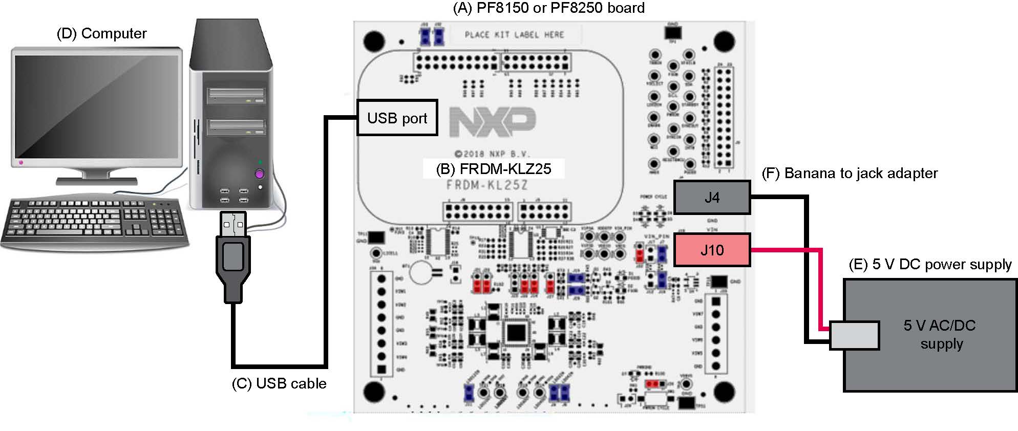
以下の手順に従って、図に示すようにハードウェアとワークステーションを構成します。
- USBケーブルをPCとFreedomボードのUSBポートに接続した状態で、評価ボードにVINを印加します
J10(VIN) およびJ4(GND) で2.5 V~5.5 Vの外部VINを供給します- ジャンパ
J17を短絡して、Freedomボードから3.3 VのVINを供給します(この動作モードは、機能の実証の目的以外に使用しないでください。このモードではレギュレーション負荷を使用できません)
- Freedomボードのリセット・ボタンを押して、ボードが適切に認識されるようにします
4. ソフトウェアのインストール
4.1 GUIのダウンロード
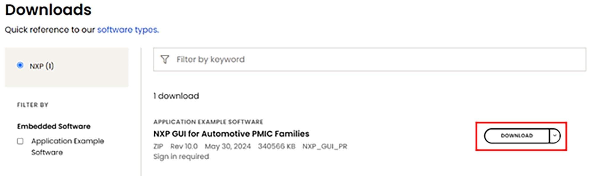
- NXPのウェブサイトにサインインし、NXPの車載用PMICファミリ向けGUIのリンクを開いて、zipファイルをダウンロードします。GUIに関する利用規約を読み、すべてを承諾したら同意します。選択した場所へのダウンロードが開始されます
- GUIパッケージが保存されたフォルダの場所を参照し、ファイルを解凍してそれらを開きます。フォルダには、以下に示すファイルが含まれているはずです。
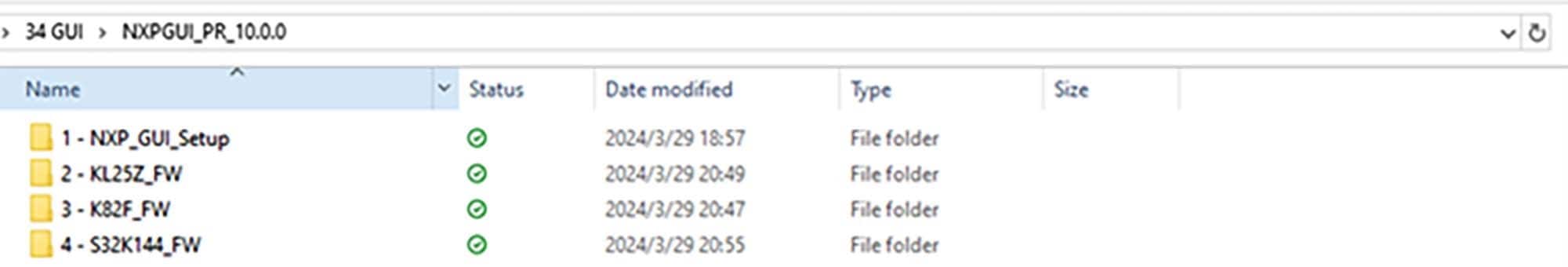
4.2 GUIをインストールして開く
- 「
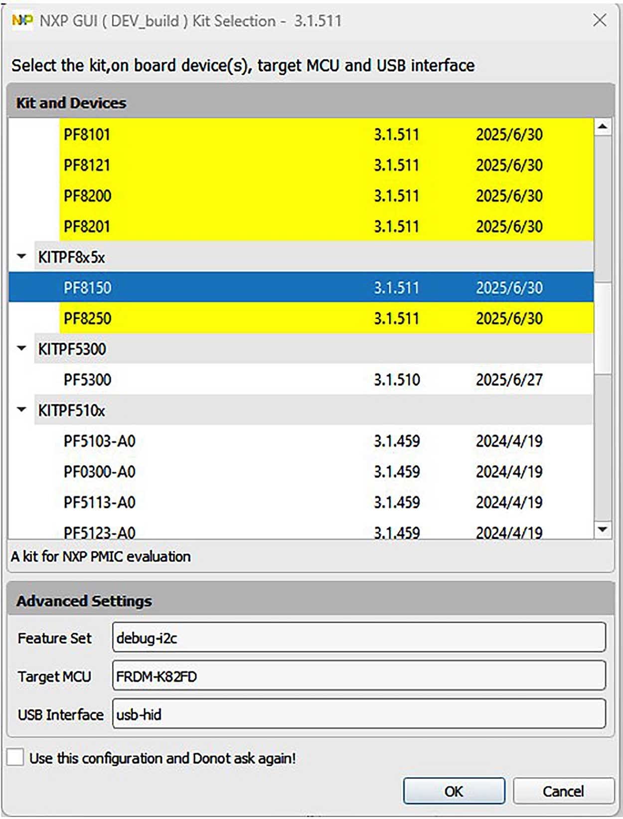
1-NXP_GUI_Setup」フォルダを開き、「NXP_GUI-10.0.0-Setup.exe」という名前のファイルをクリックすると、GUIがPCにインストールされます - インストールが完了したら、GUIを開きます。NXPの複数の車載PMIC製品をまとめた1つのGUIインターフェースが、次のように表示されます。該当する評価ボードのPMIC製品を選択し、それを開きます。例えば、評価用ボードがKITPF8150FRDMEVMの場合は、PF8150を選択して「OK」をクリックします
4.3 PF8150/PF8250ファームウェアのアップデート
FRDM-KL25Z Freedomボードは、GUIとPMICおよび他のI²Cデバイスとのインターフェースとなる通信ブリッジとして使用されます。ファームウェアは、次の3つのレベルで構成されています。
- 最初のレベルでは、SDAがブートローダを使用して、SDAプロセッサの機能コードをフラッシュするためのメイン・パスとして動作します。ブートローダはFRDM-KL25Z Freedomボードに事前プログラム済みであり、Freedomボードに恒久的な損傷が生じるのを避けるため、再フラッシュできないようになっています
- 2番目のレベルでは、SDAがKL25Z MCUファームウェアのドラッグ&ドロップによるアップデートのためのファームウェア・ローダを提供します
- 3番目のレベルでは、KL25Z MCUが、デジタルI/OやPMICへのI²C通信を制御するためにUSBの通信をMCUの命令に変換するGUIファームウェアを提供します
FRDM-KL25Zに、今後のソフトウェア・アップグレードに対応できる適切なファームウェアがロードされていない場合は、簡単な手順でファームウェアをアップデートできます。
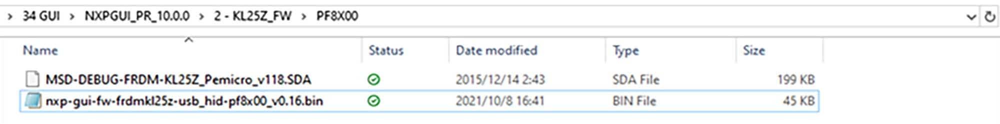
FRDM-KL25Zファームウェア・ローダのフラッシュ
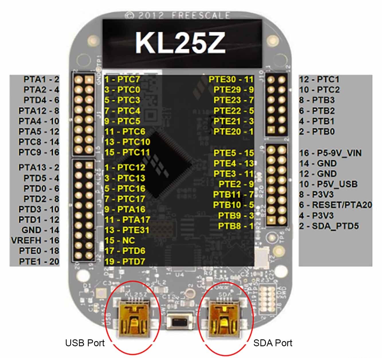
- Freedomボードのプッシュ・ボタンを押して、USBケーブルをFreedomボードのSDAポートに接続します。ファイル・エクスプローラの左側のペインに新しいブートローダ・デバイスが表示されます
- ファイル
MSD-DEBUG-FRDM-KL25Z_Pemicro_v118.SDAをドラッグして、ブートローダ・ドライブに入れます。このファイルはKL25Z_FWフォルダに格納する必要があります - USBケーブルを取り外し、(今回はプッシュボタンを押さずに)SDAポートに接続し直します。FRDM_KL25Zという新しいデバイスがPCにインストールされます
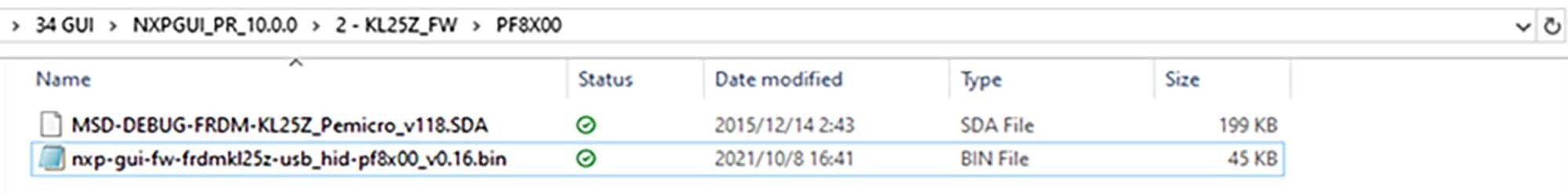
GUIファームウェアのフラッシュ
新しいソフトウェアまたはシリコンのリリースでFRDM-KL25Z Freedomボードのファームウェアのアップデートが要求される場合は、必要に応じて、次の手順に従ってFreedomボードのファームウェアをアップグレードまたはダウングレードします。この手順はファームウェアをアップデートする際にのみ必要であり、変更する必要がなければスキップできます。
- SDAポートにUSBケーブルを接続します(プッシュ・ボタンは押しません)
- インストールするGUIドライバの「
.bin」ファイル(例えば、nxp-gui-fw-frdmkl25z-usb_hid-pf8x00_v0.16.bin)を、FRDM_KL25Zのドライバ・フォルダにドラッグします - Freedomボードのファームウェアが正常にロードされました
設計・リソース
ボードに関するドキュメント
ソフトウェア
その他の参考情報
PF81- PF82のページに加えて、以下のページもご覧ください。
製品ページ
- i.MX8X:i.MX 8Xファミリ - Arm® Cortex®-A35、3Dグラフィックス、4Kビデオ、DSP、DDRの誤り訂正符号 (ECC)
- S32V234:フロント・ビュー・カメラ、サラウンド・ビュー・カメラ、機械学習、センサ・フュージョン向けのビジョン・センサ