Getting Started with the KITPF5024FRDMEVM
このドキュメントの内容
-
Get Started
-
Get to Know the Hardware
-
Configure Hardware
-
Install Software
サインイン 進行状況を保存するには アカウントをお持ちでない方 アカウントを作成する。
お客様の KITPF5024FRDMEVM | PF5024 Evaluation Board
1. Get Started
1.1 Kit Contents/Packing List
The KITPF5024FRDMEVM contents include:
- Assembled and tested KITPF5024FRDMEVM connected to FRDM-KL25Z in an anti-static bag
- 3.0 ft. USB-STD A to USB-B-mini cable
- Quick Start Guide
1.2 Additional Hardware
In addition to the kit contents, the following hardware is necessary or beneficial when working with this kit.
- Power supply with a range of 2.5 V to 6.0 V and current limit set initially to 100 mA
1.3 Windows PC Workstation
This evaluation board requires a Windows PC workstation. Meeting these minimum specifications should produce great results when working with this kit.
- USB-enabled computer with Windows 7 or Windows 10
1.4 Software
Installing software is necessary to work with this evaluation board.
- NXP_GUI_ PR_1.0: Software interface GUI, tool to configure OTP, generate TBB and OTP scripts
2. Get to Know the Hardware
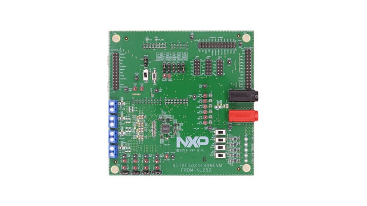
2.1 Board Description
The KITPF5024FRDMEVM evaluation board is the complete evaluation kit of the PF5024 power management IC from NXP Semiconductors. This user guide describes the functionality of the evaluation board, explains how to use the PMIC device in an application environment and gives details about the hardware and software required.
The KITPF5024FRDMEVM board is the dedicated kit for the PF5024 PMIC but it is also compatible with other PMIC devices in the family like the PF5020 and PF5023.
2.2 Board Features
SW1andSW2in single-phase mode (default) or multiphase mode up to 3.5 A peak each- PWRON switch for global wake-up or enable
- Individual enable control switch for each regulator
- LEDs to indicate individual PGOODx and global PGOOD status
- USB interface through FRDM-KL25Z for register access, TBB mode and OTP programming
- Multiple signal connectors for easy access
- Terminal blocks and test point for all the regulators for easy testing and evaluation
2.3 Board Components
Overview of the KITPF5024FRDMEVM evaluation board.
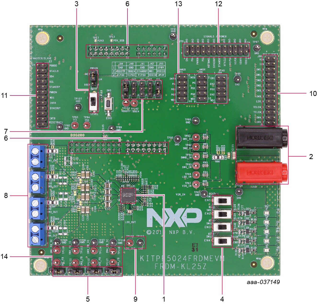
- PF5024 PMIC
- VIN connector
- PWRON control switch and jumper
- Enable switches for the regulators
- Feedback jumpers for the buck regulators
- FRDM-KL25Z connectors (for SW/GUI interface) on the bottom side of the board
- Jumpers for IO control (TBBEN, VDDOTP, STANDBY, WDI, VDDIO)
- Load terminal for the buck outputs
- Load / test point for LDO1 output
- Connector for efficiency measurement
- Connector for leader/follower (multi-PMIC) connection
- Connector for signals and power measurement
- Connectors for IO measurement
- Feedback test points of buck regulators to measure loop stability
3. Configure Hardware
3.1 Configuring the Hardware for Setup
To configure the hardware and workstation, complete the following procedure:
-
With the USB cable connected to the PC and the USB port in the Freedom board, apply VIN to the evaluation board
- Provide external VIN between 2.5 V to 5.5 V on
J10(VIN) andJ4(GND). Make sure that the supply is currently limited to 100 mA
- Provide external VIN between 2.5 V to 5.5 V on
- Press Reset on the Freedom board, to ensure that board is properly recognized
- If the NXPGUI application was not installed before, perform Step 6 of Section 4.2 "Freedom Board Bootloader Refresh in a Windows 7 or 10 System" to install it for the first time. Open the NXPGUI application from the installation folder or from the Start menu
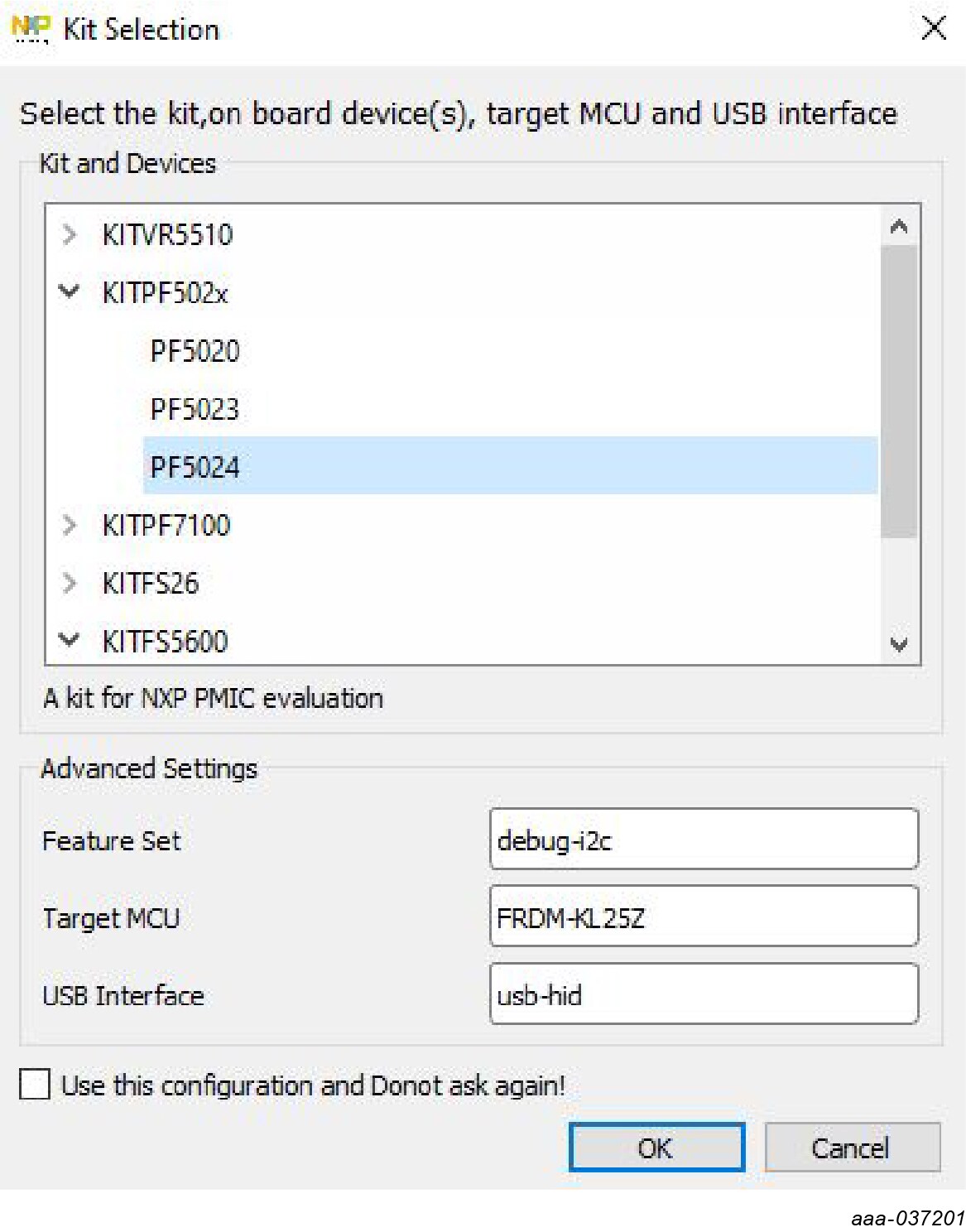
- A configuration window is displayed. Select one of the devices to load the predefined configurations, and then click OK
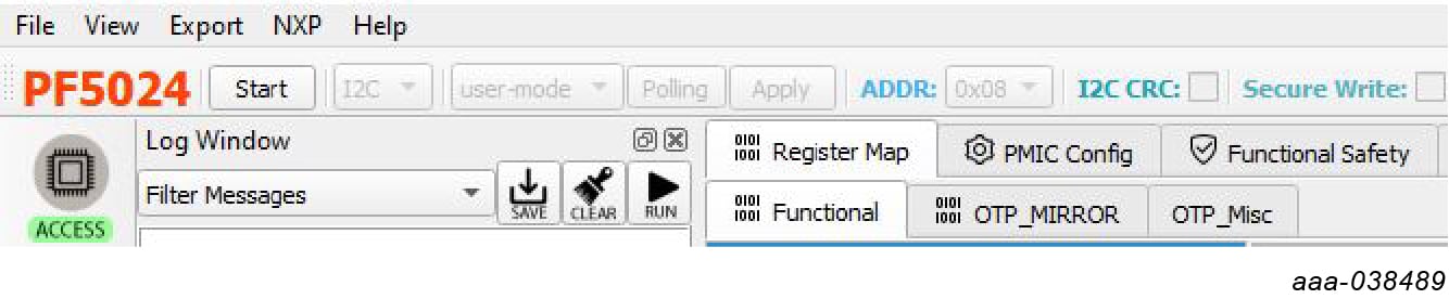
- The NXPGUI interface should open and load the main framework. Make sure to confirm if the GUI can identify the USB device properly. This is displayed by the active Start button on the top-left corner of the GUI
- Click Start to enable the connection to the device. The device status can be read from the bottom-left corner of the GUI
- Once the device is connected, the system is ready for Hardwire, TBB or OTP operation as desired
4. Install Software
4.1 Installing and Configuring Software and Tools
Download and unzip the NXP_GUI_ PR_1.0 file into any desired location. The package should contain a GUI folder and MCU folder.
4.2 Freedom Board Bootloader Refresh in a Windows 7 or 10 System
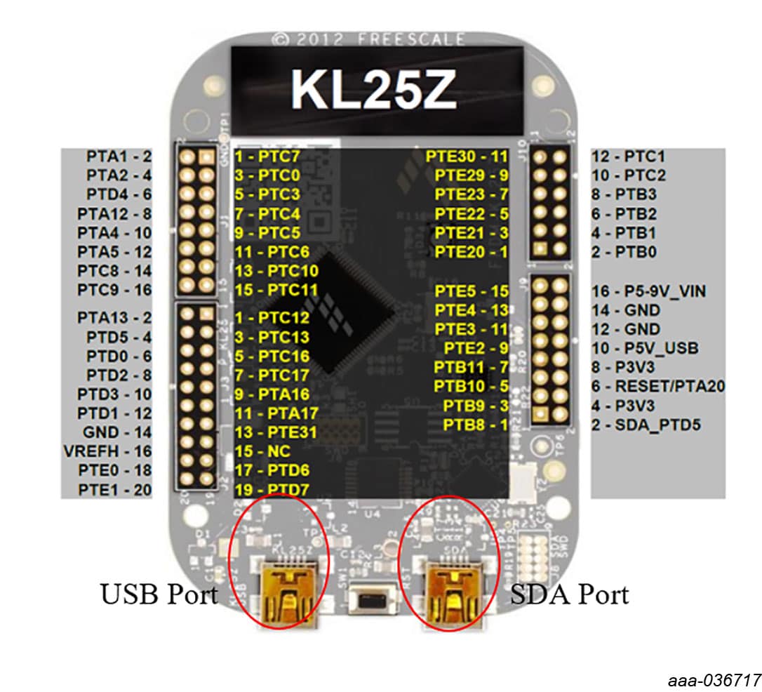
- Press the
RSTpush button on the Freedom board and connect the USB cable into the SDA port on the Freedom board. A new Bootloader device should appear on the left pane of the file explorer - Drag and drop the file MSD-DEBUG-FRDM-KL25Z_Pemicro_v118.SDA from the MCU folder into the Bootloader drive
- Disconnect and reconnect the USB cable into the SDA port (this time without pressing the
RSTpush button). The PC installs a new device called FRDM_KL25Z - Locate the file nxp-gui-fw-frdmkl25z-usb_hid-pf502x_v0.1.6.bin from the MCU folder and drag and drop the file into the FRDM_KL25Z device
- Freedom board firmware is successfully loaded
- Open and run the NXP_GUI-1.0-Setup.exe file from the GUI folder inside the unzipped package. This installs the NXPGUI software in the system. Install it in a local destination folder
4.3 Ready to Use
Start embedded application development.
Design Resources
Board Information
Additional Resources
Product Summary Page
Tool Summary Page
- KITPF5024FRDMEVM | PF5024 Evaluation Board: This page provides overview information, technical and functional specifications, ordering information, documentation and software. The Getting Started provides quick-reference information applicable to using the KITPF5024FRDMEVM board, including the downloadable assets
References
Application Pages:
Hardware Pages:
Software Pages:
Support
Forums
Connect with other engineers and get expert advice on designing with the KITPF5024FRDMEVM on one of our community sites.