Getting Started with the FRDM-AUD10 Development Board
このドキュメントの内容
-
Out of The Box
-
Get Software
-
Run And Install
-
Programming
-
Build And Run
-
Audio Software
サインイン 進行状況を保存するには アカウントをお持ちでない方 アカウントを作成する。

お客様の FRDM AUD10、HiFi 5オーディオDSP、Arm Cortex-M7 MCU
1. Out of The Box
The development kit includes:
- FRDM-AUD10 evaluation board
- Quick Start Guide
The user needs to prepare two USB-Type C cables and one RJ45 Ethernet cable.
To begin developing the user’s application on the AUD10 follow the detailed instructions provided below.
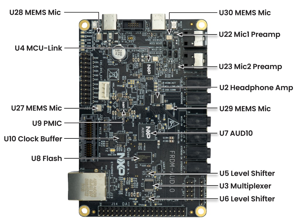
1.1 Get Familiar With The Board
1.2 Board Cable Connections
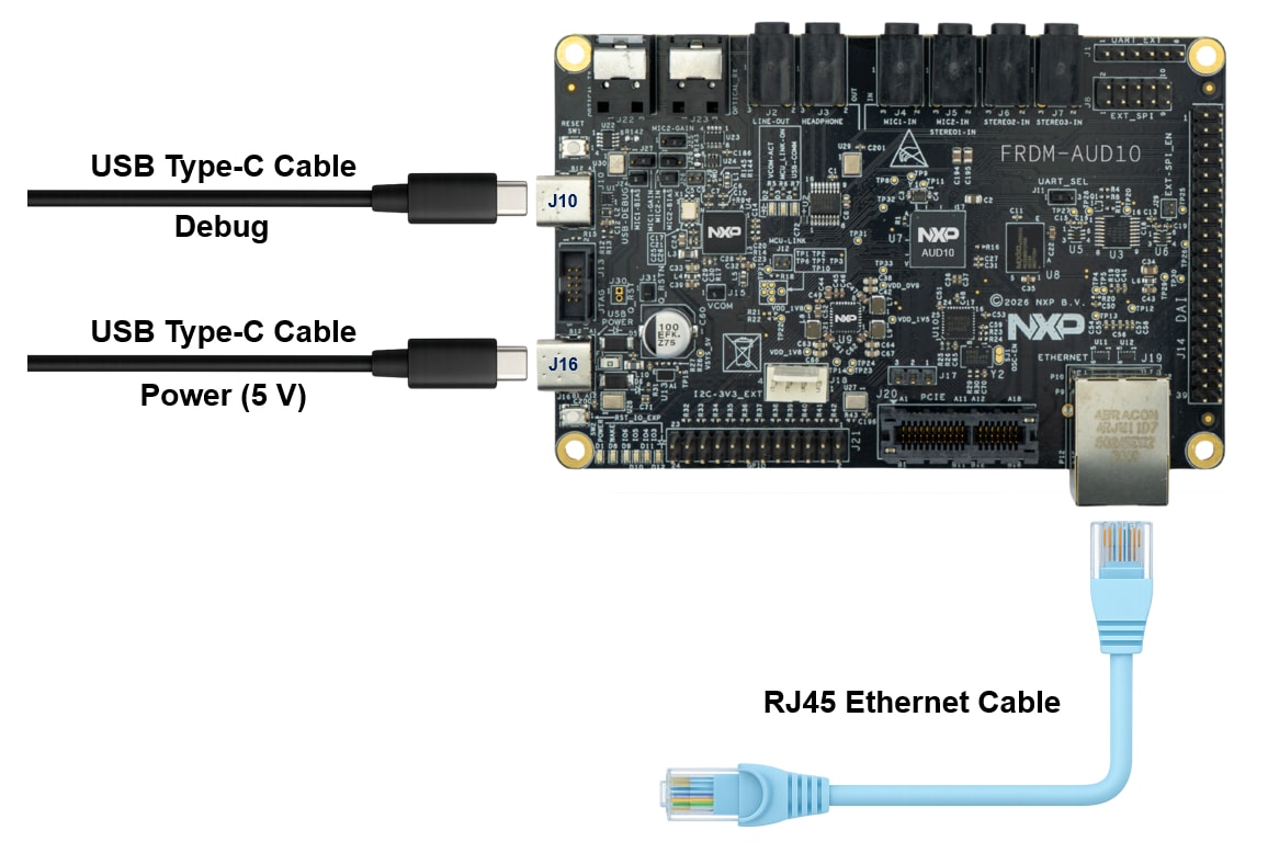
Connect a USB-Type C cable to the USB-Type C power connector (J16) to provide 5 V power.
The user can use the GUI to control the AUD10 via MCU-Link and/or Ethernet.
Control AUD10 via MCU-Link: Connect a USB-Type C cable to the USB-Type C debug connector (J10), then
connect the other end of the cable to the PC.
Control AUD10 via Ethernet: Connect the FRDM-AUD10 board to the PC using an RJ45 Ethernet cable. Please note that a direct connection is required. Do not connect through a network switch, as network switches are currently not supported.
1.3 Bootstrap Modes
The GPIO0 and GPIO1 of the AUD10 are designated as the bootstrap pins.
The following table specifies the bootstrap selection for the AUD10.
| GPIO[1…0] | Boot mode description |
|---|---|
| 00 | Boot image download from external flash using SPI-M interfacing |
| 01 | Boot image send to the system via host using PCIe interface or SPI interface, host assisted boot mode. PCIe clock 100 MHz(External) |
| 10 | Boot image send to the system via host using PCIe interface or SPI interface, host assisted boot mode. PCIe clock 125 MHz(External) |
| 11 | Boot image sends to the system via host using PCIe interface or SPI interface, host assisted boot mode. PCIe clock 124.8 MHz(Internal) |
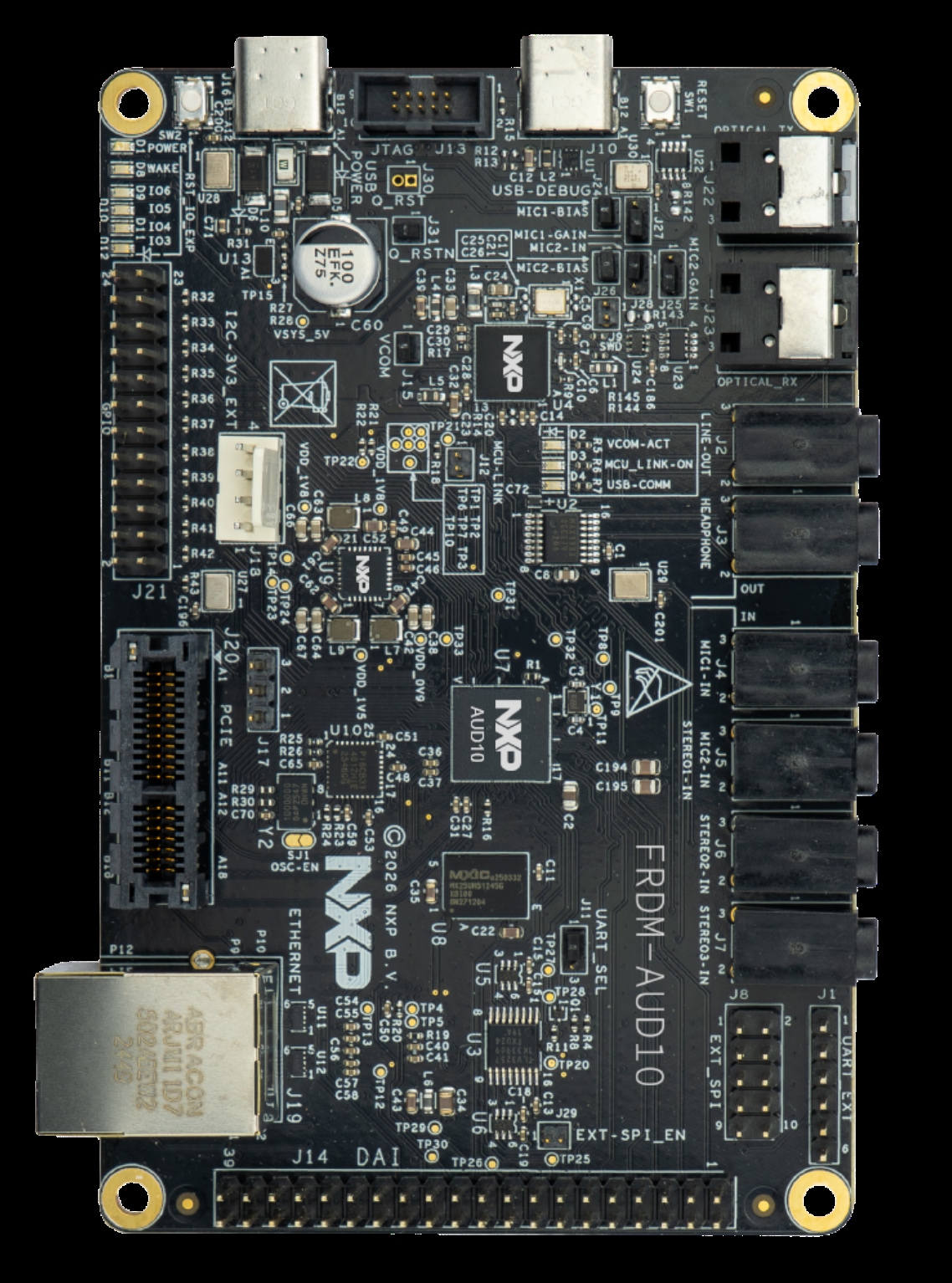
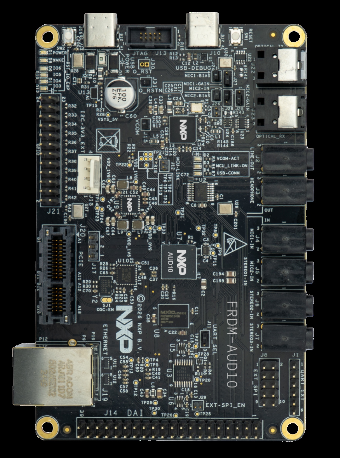
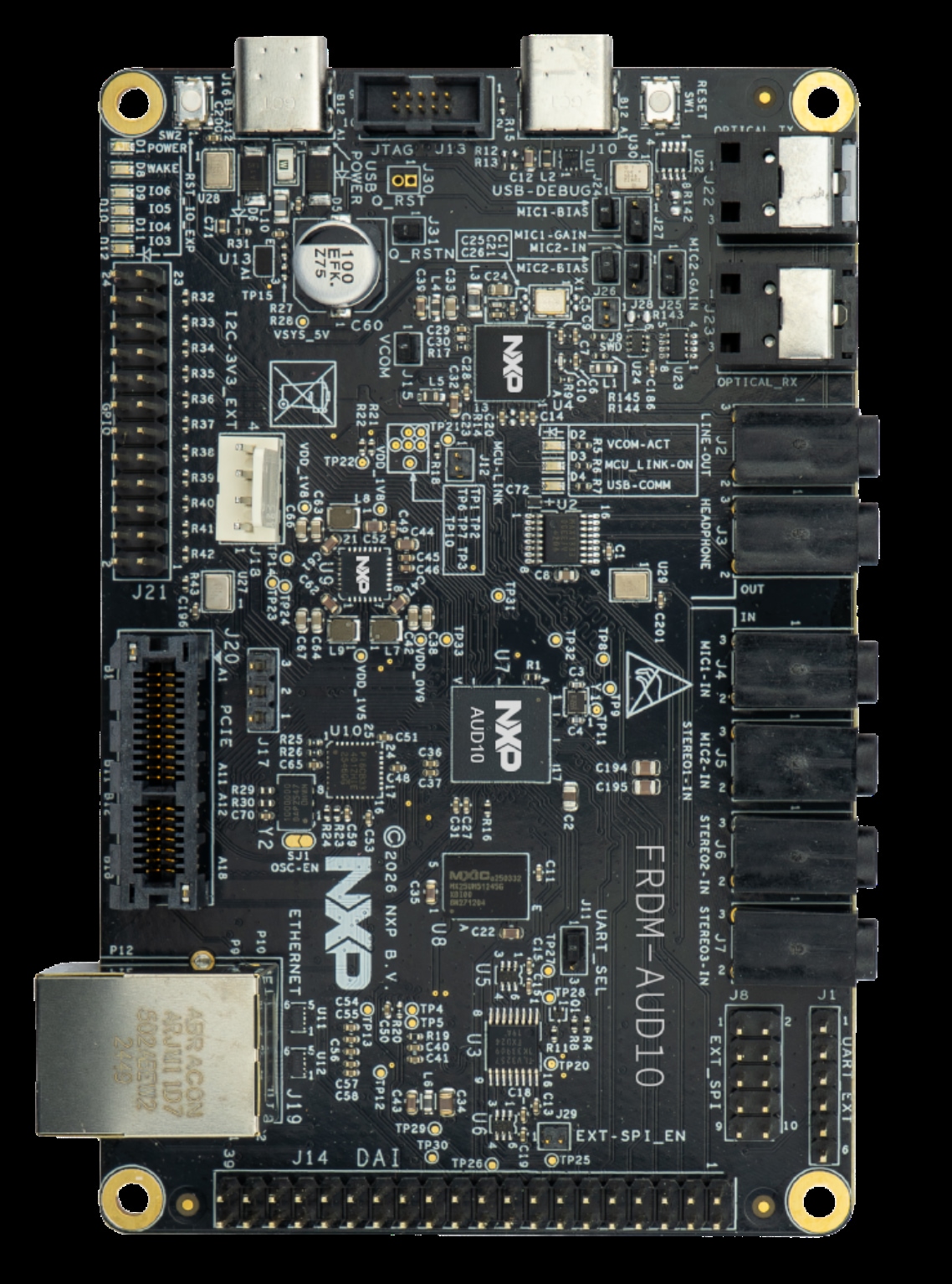
On the FRDM-AUD10 board, J21 pin pairs 23-24 and 21-22 are used to set the GPIO0 and GPIO1 levels of the
AUD10. Placing a jumper cap sets the corresponding GPIO level to 0, while removing it sets the level to 1.
J21 pin pair 23-24: To set the GPIO0 level.
J21 pin pair 21-22: To set the GPIO1 level.
Select Boot From Flash Mode For The AUD10
Place jumper caps on J21 pin pairs 23-24 and 21-22 to set both GPIO0 and GPIO1 of the AUD10 to logic 0.
GPIO[1…0] = 00, boot from flash mode is selected by the AUD10.
- GPIO0 = 0
- GPIO1 = 0
Select Host Assisted Boot Mode For The AUD10
Remove the jumper caps from J21 pin pairs 23-24 and 21-22 to set both GPIO0 and GPIO1 of the AUD10 to
logic 1. GPIO[1…0] = 11, boot from flash mode is selected by the AUD10. The user can also choose to set GPIO[1..0] to
01 or 10.
- GPIO0 = 1
- GPIO1 = 1
2. Get Software
2.1 Recommended PC Configuration For GUI Installation
AUD10 GUI is designed to run on general-purpose, moderately powerful desktop PCs or laptops. The following is the recommended PC configuration:
| Operating System | Windows 10 and Above |
|---|---|
| RAM | 4 GB |
| Hard Disk SSD | SSD, with a minimum of 2 GB of free space |
| Text size | 150% |
| Display Resolution | 1920x1080 |
Users may experience intermittent disappearance of certain GUI elements (for example: combo boxes, checkboxes, radio buttons) when changing screen resolution or display scaling, particularly on systems using Intel integrated graphics. This behavior is associated with known rendering issues in some Intel GPU drivers when used with Qt-based applications.
Recommended Actions:
- Avoid changing screen resolution, switching displays or adjusting display scaling while the application is running
- If the issue occurs, restart the application to restore normal GUI behavior
2.2 Installation Prerequisites On PC
Before using the GUI, the following software must be downloaded to the user’s PC.
class="metadata">Table 3. Software Overview
| Sr No. | Software Name | Package Name | Description |
|---|---|---|---|
| 1 | AUD10 GUI installer exe | SAF9X00_GUI_R<x.y.z_yyyymmdd>_Setup.exe |
Windows OS installer package for AUD10 GUI. |
| 2 | AUD10 firmware binaries | SAF910X_101_SBL_v<x.y.z>_rel_secure.bin |
AUD10 firmware binaries would be available in the package, which needs to be loaded on the device |
SAF910X_101_CKC_S<abcd>_secure.bin |
|||
SAF910X_101_SC_QA-FRDM1.0_<x.y.z>_secure.bin |
|||
SAF910X_101_CAP_v<x.y.z>_rel_secure.bin |
|||
SAF910X_101_APP_<ABCD>_QA-FRDM1.0_<yyyymmdd-HHMMSS>_rel_secure.bin |
2.3 GUI Installation
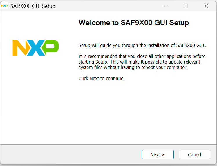
Start installing AUD10 GUI by double-clicking SAF9X00_GUI_R<x.y.z_yyyymmdd>_Setup.exe.
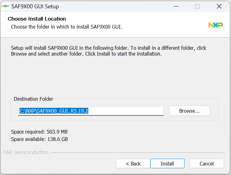
Follow the on-screen instructions to complete the installation process.
- Welcome window
- Click the "Browse..." button to select another installation folder path if needed
- Installation Progress
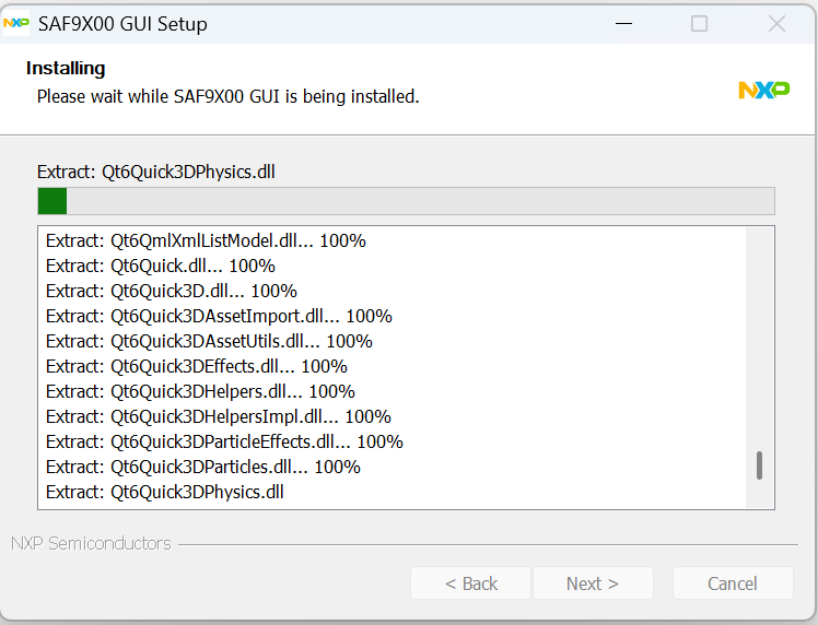
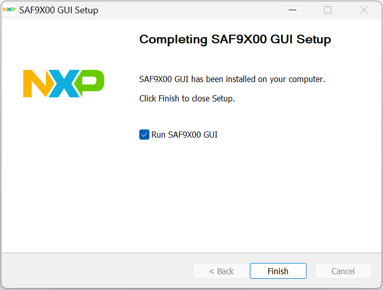
- Click the "Finish" button to complete the installation
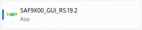
Click the Windows "Start" menu button, look for the application SAF9X00_GUI_R[version], click the AUD10 GUI Application as shown in the Figure
The following screen appears on a successful launch.
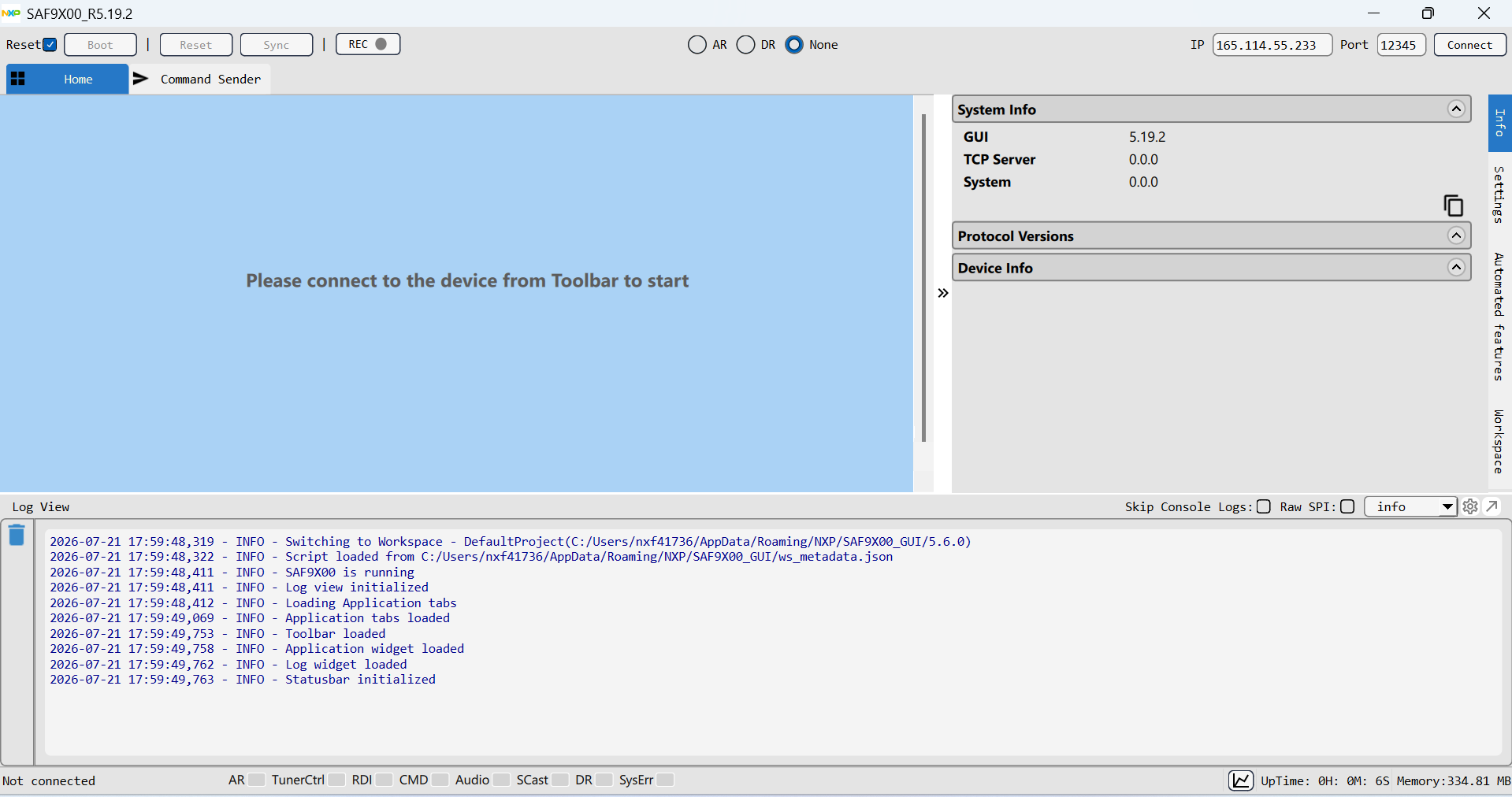
Users can verify the installed GUI version from the title bar of the GUI.
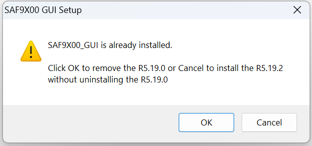
If any earlier version of the AUD10 GUI is installed on the system, a pop-up will appear, requesting the user to press OK to uninstall the earlier version or press Cancel to install without uninstalling the earlier version.
Configure The PC’s Ethernet Adapter IP Address
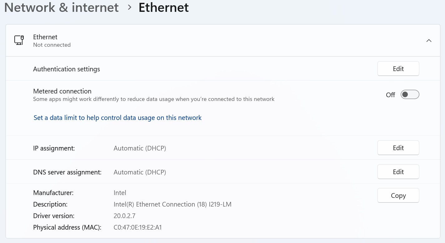
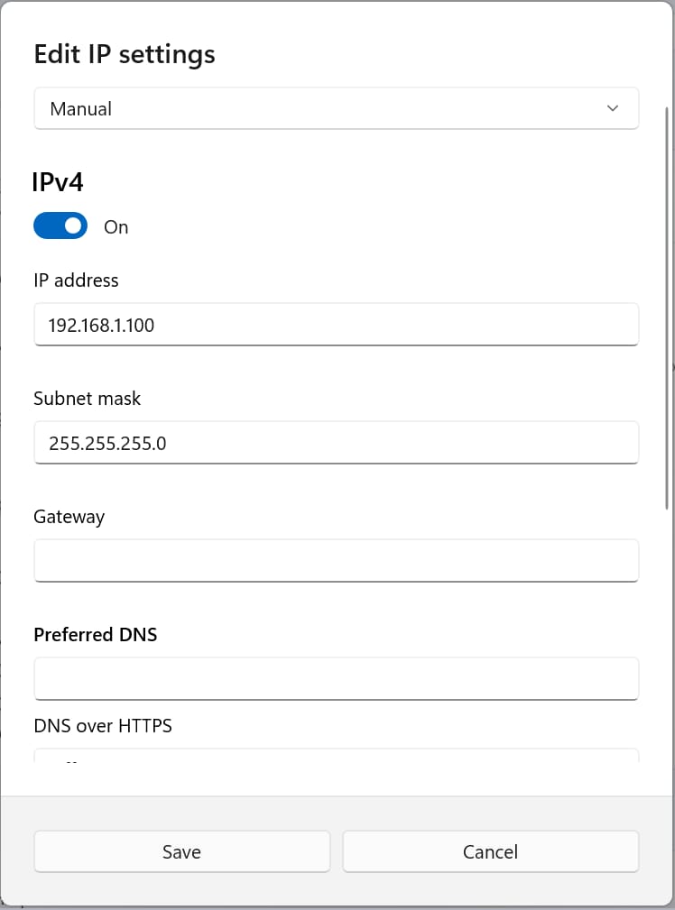
To control the AUD10 via Ethernet, the PC's Ethernet adapter must be configured with an IP address on the same subnet as the AUD10.
The AUD10 uses the static IP address 192.168.1.80. assigns the PC an unused IP address in the
192.168.1.x subnet (for
example, 192.168.1.100) and ensures that there are no IP address conflicts on the network.
2.4 TCP Server
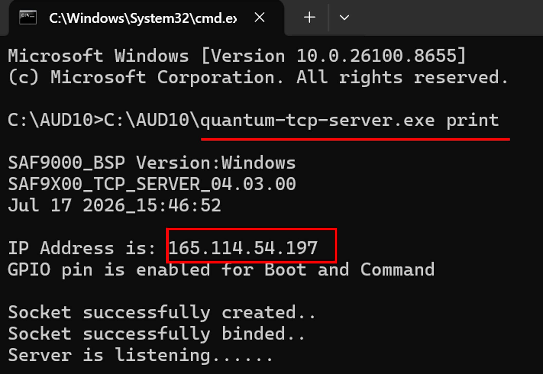
Run quantum-tcp-server.exe print in a Command Prompt window on the PC.
The TCP Server IP address will be displayed in the Command Prompt window.
For example:
3. Run And Install
3.1 Boot The AUD10 via MCU-Link
The following steps describe how to use the GUI to boot the AUD10 via MCU-Link.
- Refer to Section 1.3.2 to select Host Assisted Boot Mode for the AUD10
- Refer to Section 2.2 to run the TCP Server and obtain its IP address
- Open the GUI, enter the TCP Server IP address and Port number (12345), then click the "Connect" button. Check
if the GUI is connected to TCP Server successfully
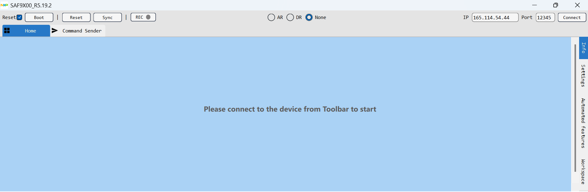

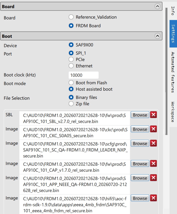
- In the Settings tab, set Board to FRDM Board, Port to SPI_1, and Boot mode to Host assisted boot. Set File
Selection to Binary files, then select the following firmware binaries in order:
- SBL
- CKC
- SoftConfig
- CAP
- Binary (NEEE)
- AWE or AOC Binary
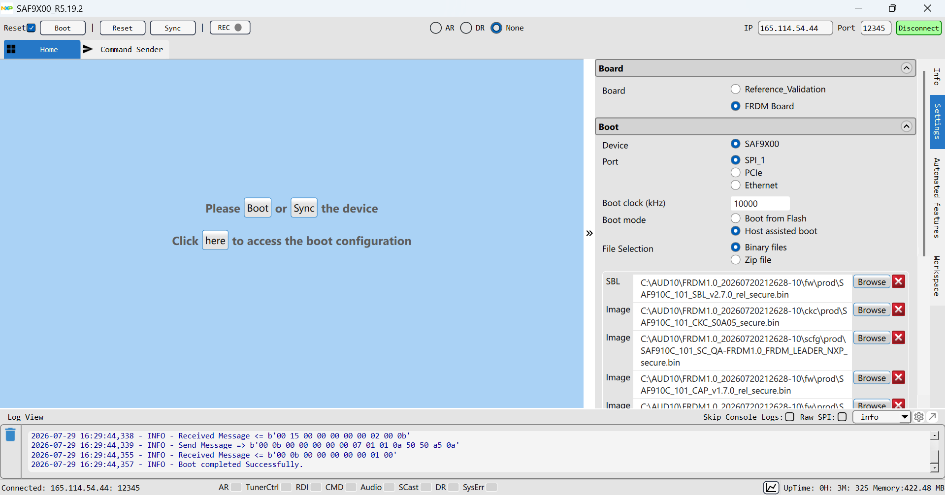
Next, click the "Boot" button to boot the AUD10.
- Check if boot is completed successfully
- Refer to Section 5 to control the AUD10 via Ethernet
4. Programming
4.1 Flash Programming
The following steps describe how to use the GUI to program the flash of the AUD10 via MCU-Link.
- Refer to Section 1.3.2 to select Host Assisted Boot Mode for the AUD10
- Refer to Section 2.2 to run the TCP Server and obtain its IP address
- Open the GUI, enter the TCP Server IP address and Port number (12345), then click the "Connect" button. Check if the GUI is connected to the TCP Server successfully
- In the Settings tab, set Board to FRDM Board, Port to SPI_1, and Boot mode to Host assisted boot. Set File
Selection to Binary files, then select the following firmware binaries in order:
- SBL
- CKC
- SoftConfig
- CAP
- Binary (FEEE)
Next, click the "Boot" button to boot the AUD10.
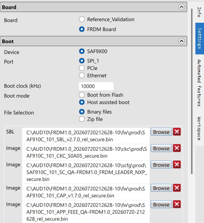
- Check if the boot is completed successfully
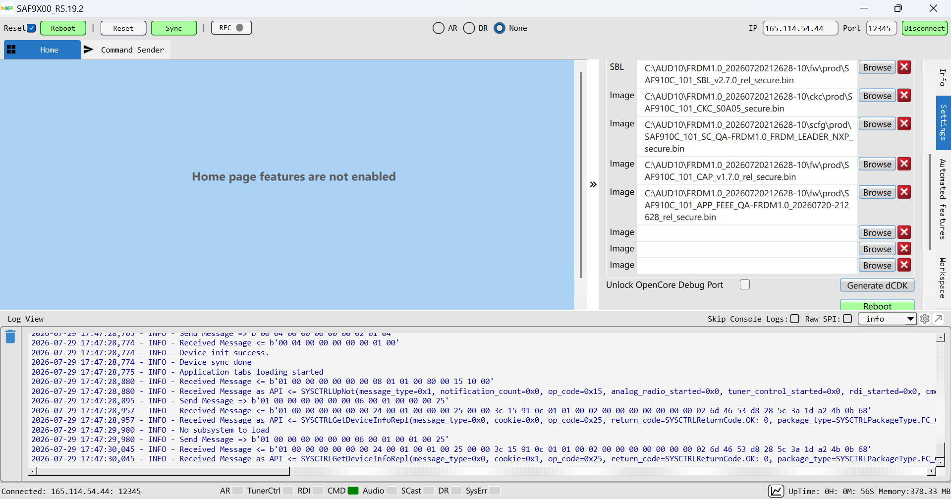
- Click the "Sync" button of the GUI, a green “LED” should show up at the bottom of the window indicating the
CMD subsystem is up
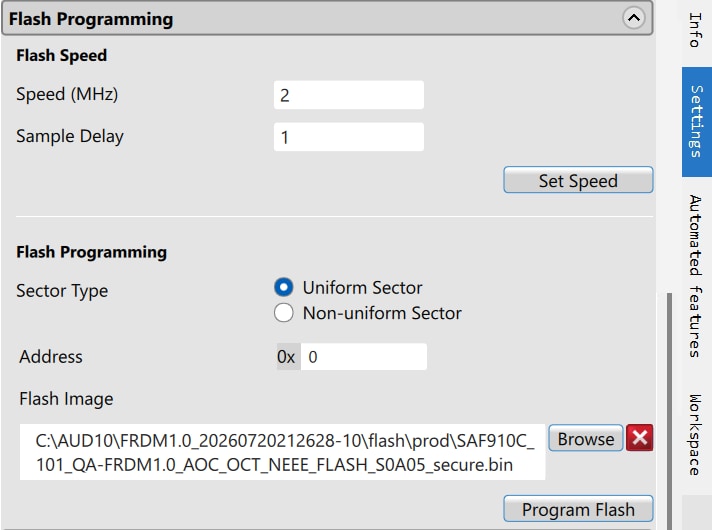
- In Setting > Flash Programming, select the appropriate flash binary, either AOC or AWE. Click the "Program
Flash" button
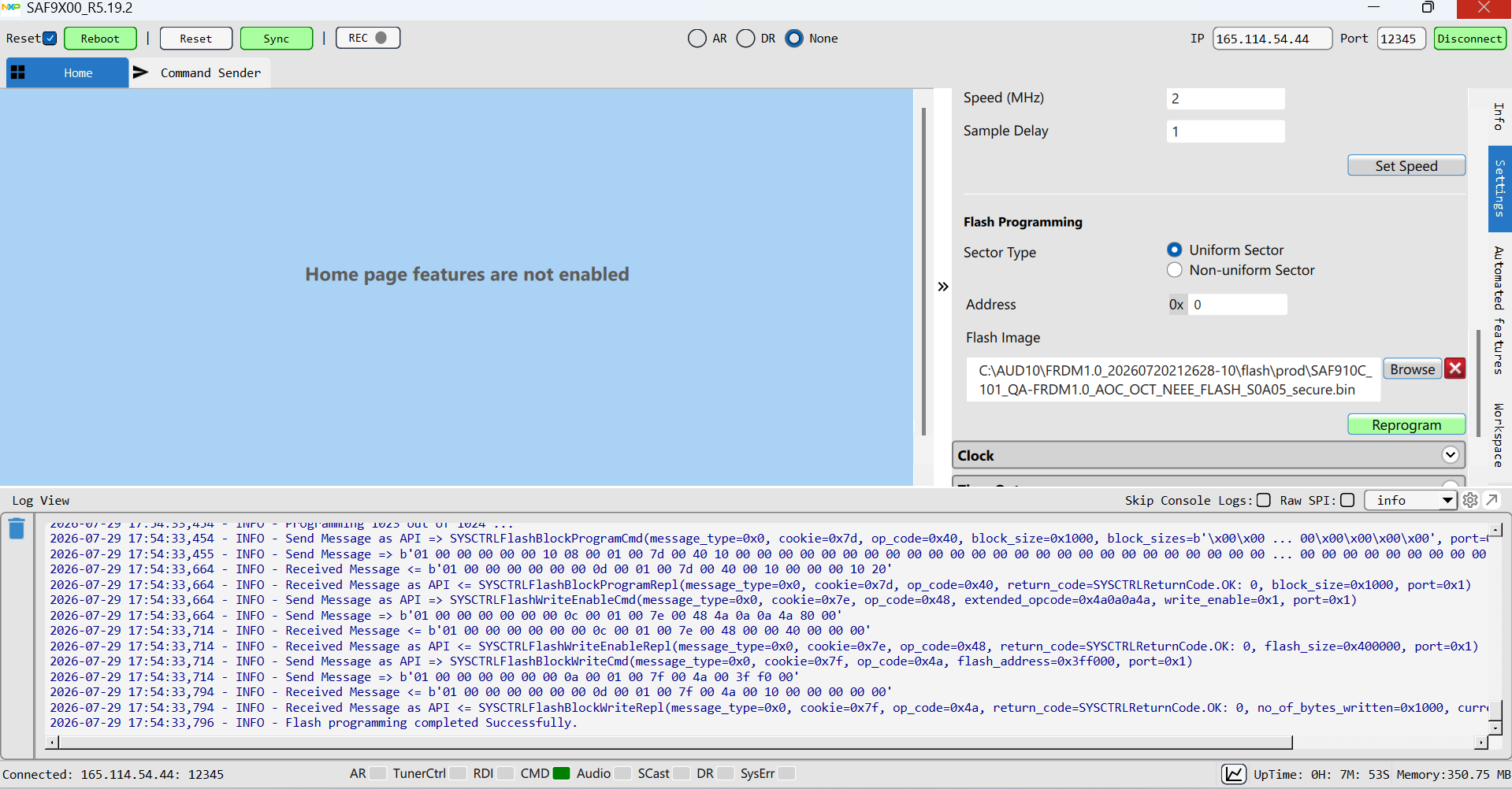
- Check if flash programming is completed successfully
- Close the TCP Server and the GUI, power off the board. Refer to Section 1.3.1 and select Boot from Flash Mode
for the AUD10. Then power the board back on. After the board boots up, verify connectivity by pinging the AUD10 at
IP
address
192.168.1.80. - Run the TCP Server and the GUI, enter the TCP Server IP address and Port number (12345) to connect the GUI to the TCP Server
- Refer to Section 5 to control the AUD10 via Ethernet
5. Build And Run
5.1 Connect The GUI To The AUD10 via Ethernet
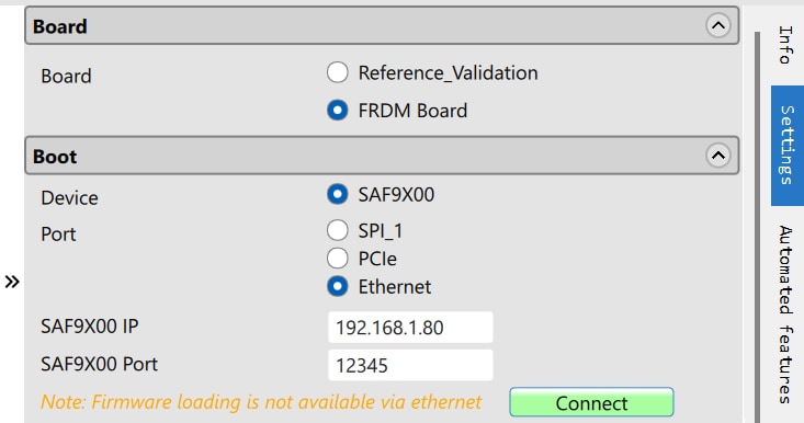
In the Settings tab, set Board to FRDM Board, Port to Ethernet. Enter the AUD10 IP address 192.168.1.80 and port
number 12345, then click the "Connect" button. Check if the GUI is connected to the AUD10 successfully.
5.2 AOC Demonstration
Early Audio is output through the Line Out (J2) and Headphone Out (J3) immediately after
the AUD10 starts.
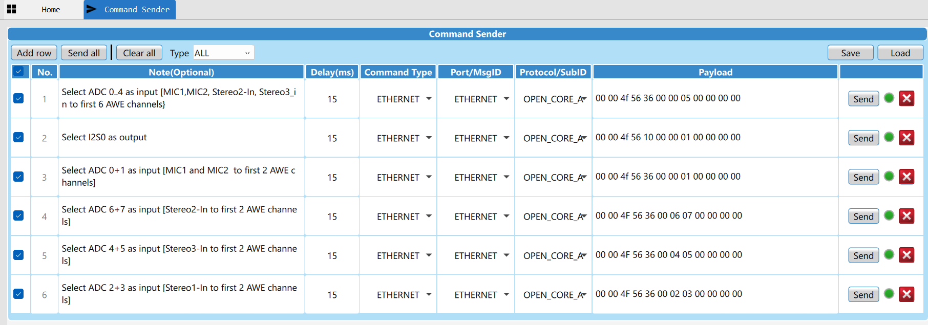
In the Commander Sender tab of the GUI, send Ethernet commands to configure the AWE input and output.
For example, after sending the following two Ethernet commands, the audio signal received on Stereo3 In
(J7) is processed by AWE and output through IIS0 out. The user can hear the processed audio through Line
Out (J2) or Headphone Out (J3).
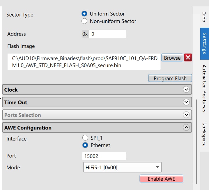
To tune the AWE project using Audio Weaver, send the following command in the GUI to enable AWE.
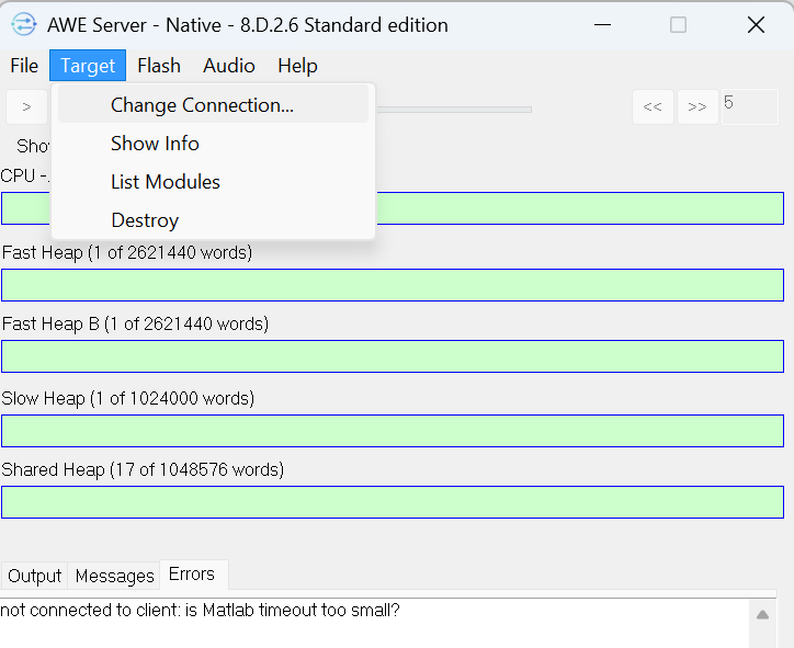
Open Audio Weaver (Version 8.D.2.6).
In AWE Server, click Target > Change Connection.
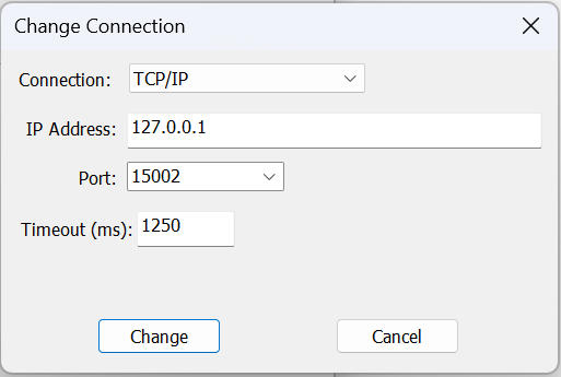
In the Change Connection window, select TCP/IP from the Connection drop-down list and enter 127.0.0.1 in the IP Address field. Then, click the "Change" button.
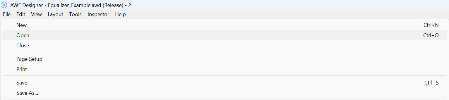
In AWE Designer, click File > Open.
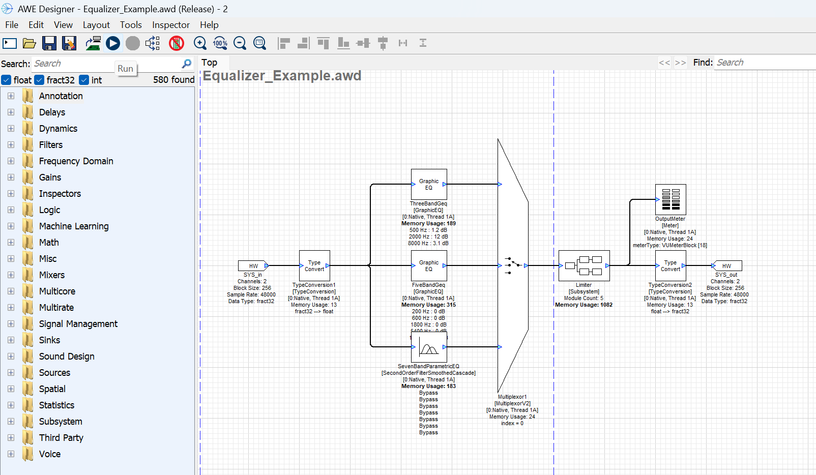
Select the desired awd project and then click the Run button.
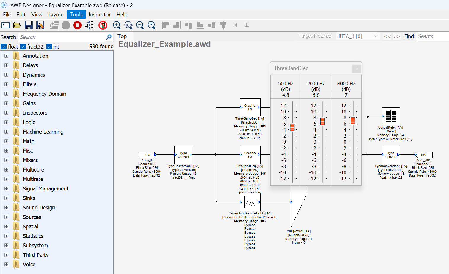
The user can double-click the desired module and adjust the parameters as needed. The sound effect will be applied immediately.
Audio Software
6.1 Audio SDK
The AUD10 Audio SDK enables users to develop applications that run on the HiFi 5 core.
Please refer to the AUD10 Audio SDK documentation for more details:
~\hifi5\aoc-frdm-sdk-1.9.0\docs\index.html