EVBMA7X2YDT1評価ボードのスタート・ガイド
このドキュメントの内容
-
パッケージの内容
-
ハードウェアの入手
-
接続
-
ビルドとロード
サインイン 進行状況を保存するには アカウントをお持ちでない方 アカウントを作成する。
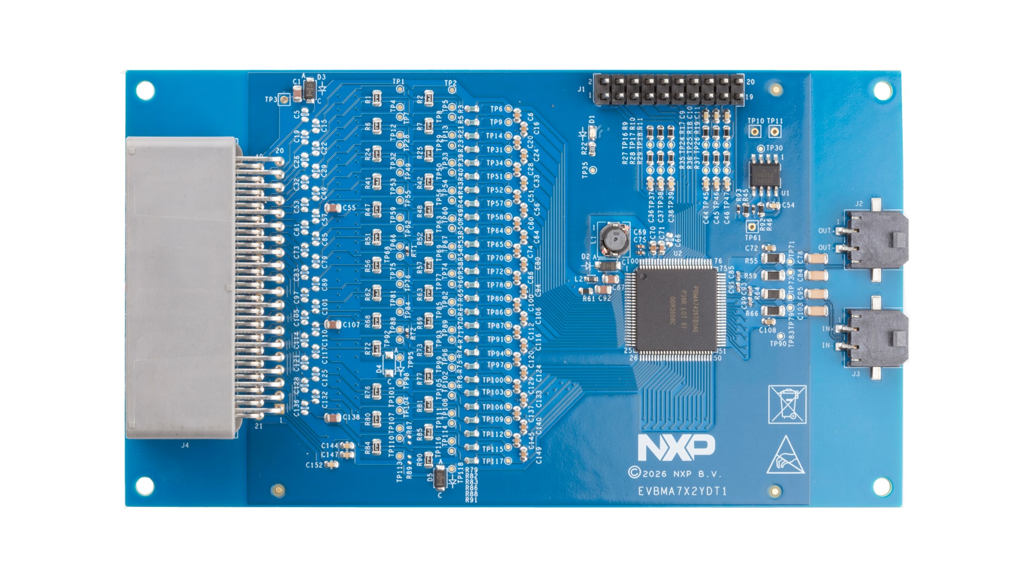
お客様の BMA7426評価ボード
1. パッケージの内容
NXPのアナログ製品開発ボードは、NXP製品の評価を目的とした使いやすいプラットフォームです。さまざまなアナログ・ソリューション、ミックスド・シグナル・ソリューション、パワー・ソリューションに対応しています。実績のある大容量テクノロジに基づくモノリシック集積回路 (IC) およびシステム・イン・パッケージ (SiP) を搭載しています。NXP製品は、システムへの電源供給において、より長いバッテリー寿命、より小さいフォーム・ファクタ、より少ない部品数、より低いコスト、より優れたパフォーマンスを実現します。
このページでは、EVBMA7X2YDT1評価ボード (EVB) をセットアップして使用する手順について説明します。
1.1 キットの内容
EVBMA7X2YDT1には以下のものが含まれています。
- 組立て済み/テスト済みの評価ボードまたはモジュール(静電気防止バッグ入り)
- 40ピン・バッテリー・セル・ケーブル x 1
- 2ピン・トランスポート・プロトコル・リンク (TPL) ケーブル x 1
1.2 追加ハードウェア
ボードを評価するには、以下の機器が必要です。
- 8セル~26セルのバッテリー・パック、またはBATT26EMULATORなどのバッテリー・パック・エミュレータ
2. ハードウェアの入手
2.1 ボードの特長
EVBMA7X2YDT1は以下の主な特長を備えています。
- デイジー・チェーン・デバイスの接続
- 動作モードを示すLEDインジケータ
- セル・バランシング抵抗(各セルにつき68 Ω)
- RC(抵抗-コンデンサ)フィルタ付きのセル検出入力
- 汎用入出力 (GPIO):デジタルI/O、レシオメトリック・アナログ入力、絶対計測によるアナログ入力
- ユーザー定義の較正パラメータを保存するためのEEPROM(電気的に消去/書き込み可能な読み出し専用メモリ)(I²C (Inter-integrated Circuit) インターフェースでICに接続)
- シリアル・ペリフェラル・インターフェース (SPI) コントローラおよびI²Cピンへの外部アクセス
2.2 ボードの説明
EVBMA7x2yDT1は、NXPのBMA7426デバイスをサポートするハードウェア評価ツールとして使用できます。詳細については、BMA742X製品ページをご覧ください。BMA7426は、エレクトリカル・トランスポート・プロトコル・リンク (eTPL) 通信機能を備えた、電気化学インピーダンス分光法 (EIS) 対応の分散型セル・モニタリング・ユニット (CMU) です。
車載用途およびインダストリアル用途での使用を想定して設計されています。このデバイスは、セルの差動電圧およびバッテリー温度測定値に対してアナログ・デジタル (ADC) 変換を実行します。EVBMA7X2YDT1は、電圧および温度の検知に関わるBMA7426ベース・アプリケーションの迅速なプロトタイプ作成に使用できます。
情報は、処理のためにマイクロコントローラにデジタル送信されます。ゲートウェイICと組み合わせて使用することで、マイクロコントローラ (MCU) のSPIデータとBMA7426のパルス・ビット情報の双方向の変換が可能です。詳細については、バッテリー通信用ICのページをご覧ください。
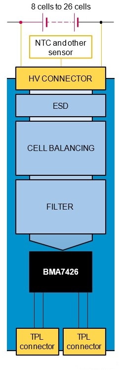
2.3 ボードのコンポーネント
EVBMA7X2YDT1を使用すると、BMA7426バッテリー・セルコントローラ (BCC) のすべての機能を実行できます。
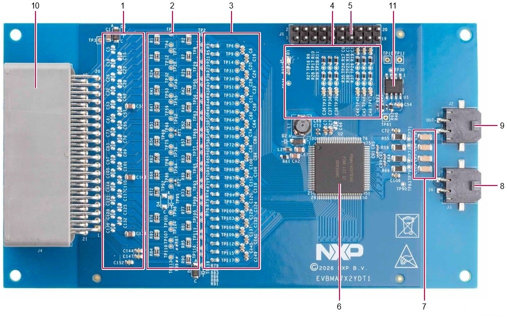
以下の表1の番号付き項目は、上記の図2の同じ番号のコンポーネントに対応しています。
表1. EVBMA7X2YDT1ボードのコンポーネントと説明
| 番号 | 名称 | 説明 |
|---|---|---|
| 1 | ESD差動コンデンサ | 差動静電気放電 (ESD) 保護 |
| 2 | セル・バランシング抵抗 | CBxピンあたり68 Ω |
| 3 | CTxローパス・フィルタ | 330 Ω/10 nF差動 |
| 4 | GPIOローパス・フィルタ | NTC接続 |
| 5 | GPIO/SPIコネクタ | 外部のNTC(負の温度係数)またはSPI/I²Cペリフェラル接続用 |
| 6 | PBMA7426TB1AE | 26セルBCC IC |
| 7 | 高電圧コンデンサ | 通信絶縁用 |
| 8 | MOLEX-43650-0213 | ゲートウェイ接続用ロー側通信コネクタ |
| 9 | MOLEX-43650-0213 | 次のノード接続用ハイ側通信コネクタ |
| 10 | JAE-MX34040NF2 | セル接続およびNTC接続用40ピン・コネクタ |
コネクタ
このセクションでは、評価ボードのコネクタの概要を説明します。
バッテリー・パック・コネクタJ4
セル接続およびNTC接続はJ4で利用できます(図3を参照)。
セル0はC0M (cell0M) とC1M (cell0P) 間に接続され、セル1はC1M (cell1M) とC2M (cell1P) 間に接続されます。以降も同様です。セル17は、C17M (cell17M) とC17P (cell17P) 間に接続されます。
C17P-PWRおよびGND(ピン21)は、EVBMA7X2YDT1への給電に使用され、評価ボードの消費電流に伴う電圧降下を避けるために、それぞれC17PおよびC0Mから分離されています。
下側のセルについては、セル25はC25MとC24M間に接続され、セル24はC24MとC23M間に接続されます。以降も同様です。セル接続とスタックの配置については、以下のボード回路図を参照してください。オプションの外部10 kΩ NTCセンサは、各NTCx端子と1つのGND端子間に接続できます。
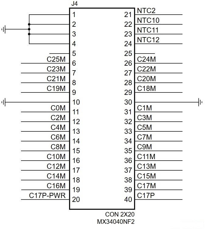
- ボード・コネクタ品番:MX34040NF2(メーカー:JAE)、40ピン、直角バージョン
- 対応する嵌合コネクタ品番:MX34040SF1
- 嵌合コネクタ用圧着端子品番:M34S75C4F1(適用ケーブル・サイズ:0.22 mm²~0.35 mm²)
TPLコネクタ
上位ノードおよび下位ノードへの絶縁接続は、それぞれJ2およびJ3を介して行う必要があります。
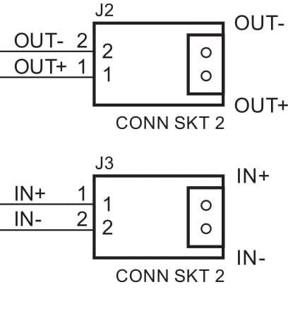
- ボード・コネクタ品番:Micro-Fit(メーカー:Molex)3.0 43650-0213、2ピン、直角バージョン
- 対応する嵌合コネクタ品番:0436450200
- 嵌合コネクタ用圧着端子品番:0436450201
- ツイスト・ケーブル:64920108(メーカー:Kromberg & Schubert)
3. 接続
3.1 接続
EVBMA7X2YDT1にはソフトウェアは付属していません。EVBMA7X2YDT1をサポートし、迅速な評価を可能にする複数のソフトウェア・バンドルが利用可能です。最適な評価環境の選択については、NXPのセールス・サポートにお問い合わせください。
4. ビルドとロード
4.1 ビルドとロード
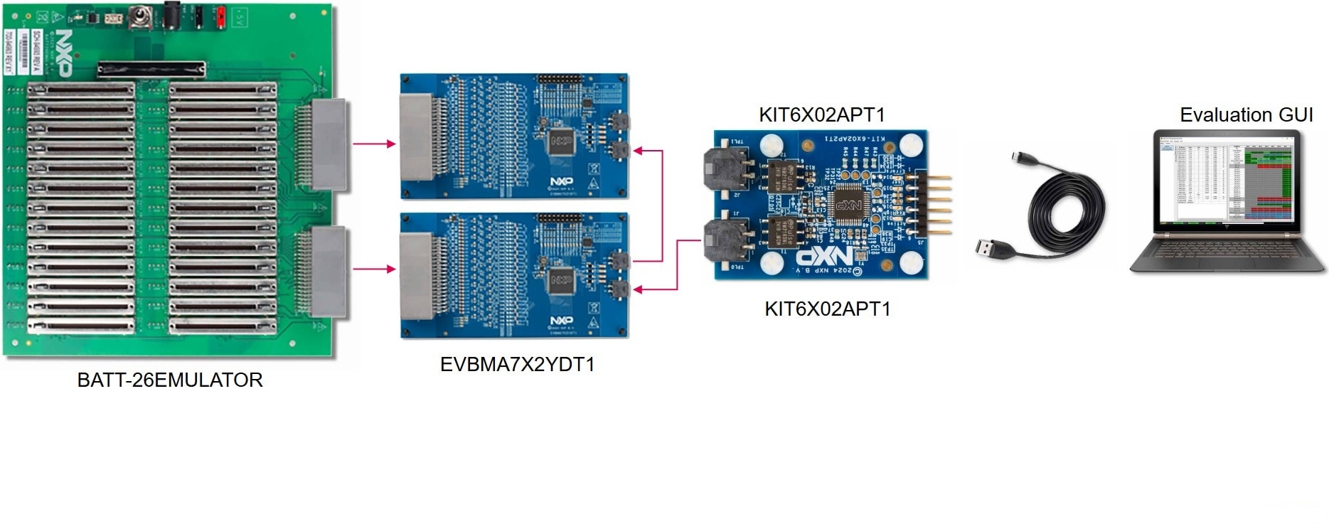
図5に、この評価ボードの完全なセットアップを示します。このセットアップでは、BATT26EMULATORを使用して、2つのEVBMA7X2YDT1ボードのセル電圧を供給およびエミュレートします。KIT-PC2TPLEVBは標準PCと通信するために接続されています。評価用グラフィカル・ユーザー・インターフェース (GUI) は、測定された電圧を表示し、BMA7x2yデバイスの操作を可能にします。実際のバッテリー・セルや別のTPL通信源など、評価の範囲に応じて、システムは異なるコンポーネントを使用できます。
設計・リソース
ボード情報
EVBの回路図、ボード・レイアウト、および部品表は、EVBMA7X2YDT1のページで入手できます。