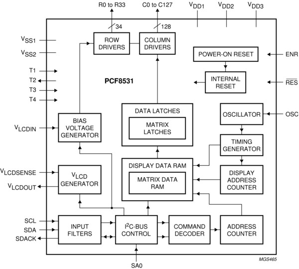
The PCF8531 is a low-power CMOS LCD row and column driver, designed to drive dot matrix graphic displays at multiplex rates of 1:17, 1:26, and 1:34. Furthermore, it can drive up to 128 icons. All necessary functions for the display are provided in a single chip, including on-chip generation of VLCD and the LCD bias voltages, resulting in a minimum of external components and low power consumption. The PCF8531 is compatible with most microcontrollers and communicates via a two-line bidirectional I²C-bus. All inputs are CMOS compatible.
Remark:The icon mode is used to reduce current consumption. When only icons are displayed, a much lower operating voltage (VLCD) can be used and the switching frequency of the LCD outputs is reduced. In most applications it is possible to use VDD as VLCD.