Getting Started with the Remote I/O Platform (RIOP)
このドキュメントの内容
-
Out of the Box
-
Install and Set Up Software (SW)
-
Get to Know the Hardware
-
Configure Hardware
-
Run the Application
サインイン 進行状況を保存するには アカウントをお持ちでない方 アカウントを作成する。
お客様の リモートI/Oプラットフォーム
1. Out of the Box
NXP's Remote I/O Platform (RIOP) accelerates industrial automation by providing flexible, high-precision data acquisition and secure, multi-protocol connectivity for factory and process control systems. RIOP simplifies integration into Industry 4.0 environments, supports predictive maintenance and optimizes reliability and operational efficiency for customers.
1.1 Kit Content and Packaging List
The kit contents include:
- An evaluation board (assembled and tested) in an antistatic bag
- USB micro-B cable
- 24 V power adapter
- Three colored wires
1.2 Additional Hardware
In addition to the contents listed above, the kit also includes an Ethernet cable.
1.3 Minimum System Requirements
Operation of the evaluation board requires a Windows PC workstation with the following properties:
- Windows 10 and up
- Available Ethernet port or a USB-to-Ethernet adapter
1.4 Software and Tools Prerequisites
To use this evaluation board, you must install the following software. All the required software is available on the information page for the evaluation board.
- Download and install FreeMASTER 3.2
- Download and unzip the source code provided on our Application Code Hub (ACH) and GitHub pages
2. Install and Set Up Software (SW)
The kit comes with a pre-programmed out-of-the-box experience demo application. To run it, configure an Ethernet port (by following the instructions in this chapter) and install FreeMASTER 3.2.
2.1 Install FreeMASTER 3.2
- Download the FreeMASTER tool 3.2 Windows installer
- Next, install the tool by following the instructions from the installation wizard
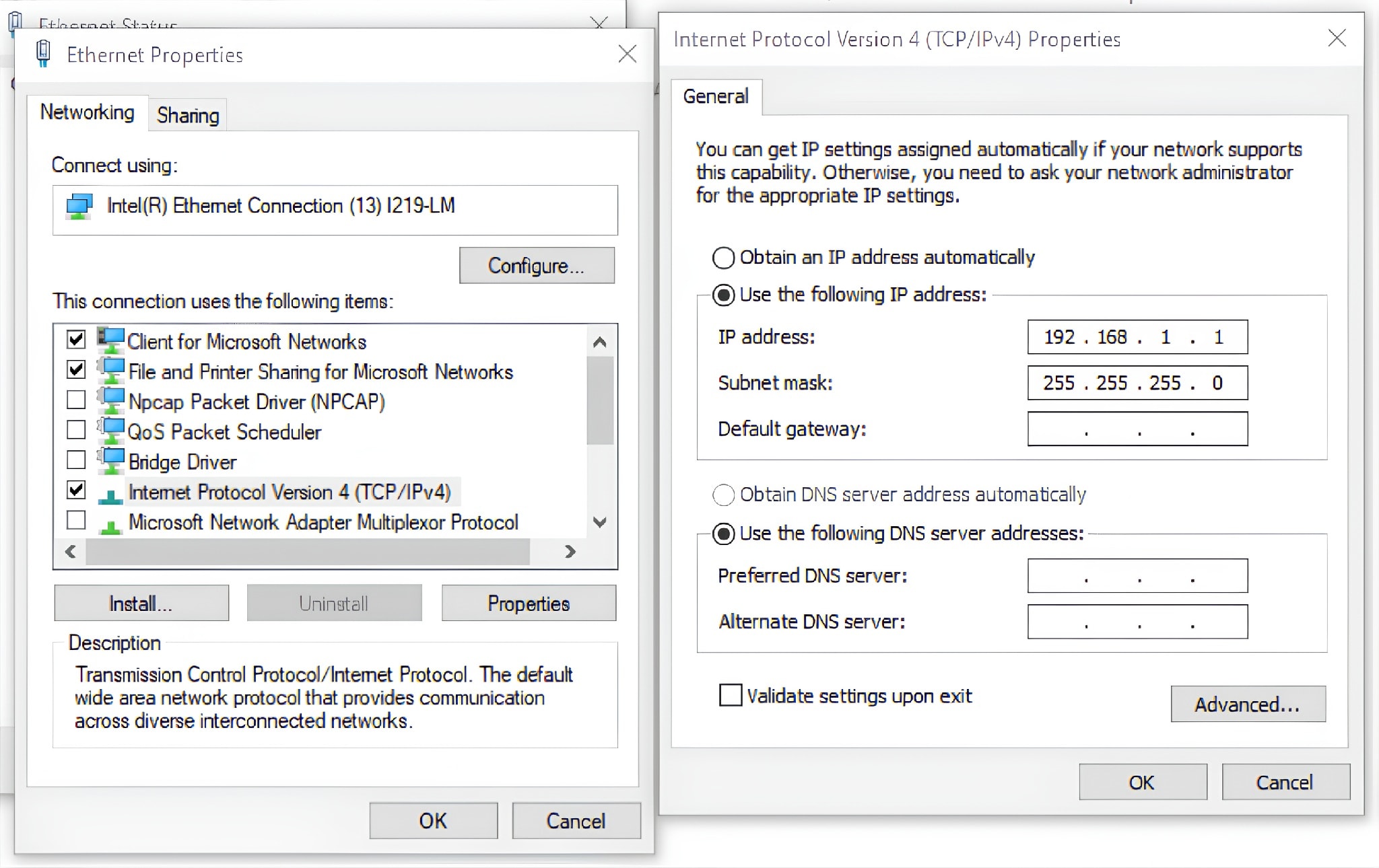
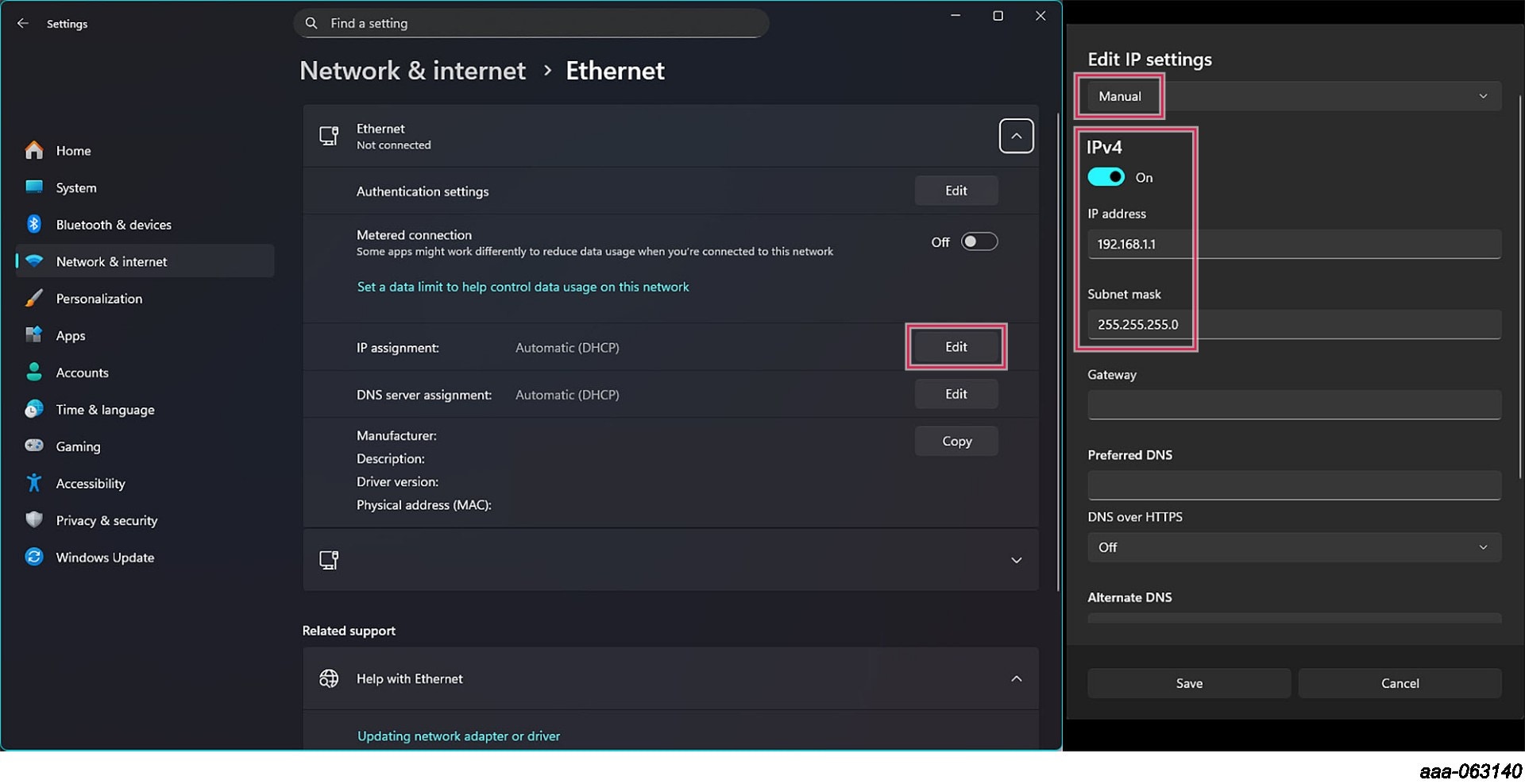
2.2 Configure the Ethernet Port
- Open Windows Settings
- Go to "Network and Internet"
- Open the "Status" tab
- Click on "Change adapter options"
- Right-click on the Ethernet port you want to use, then open "Properties"
- Select "Internet Protocol Version 4 (TCP/IPv4)", then click on "Properties"
- Configure the properties to the IP address
192.168.1.1and the subnet mask to255.255.255.0, like in Figure 1 or Figure 2
3. Get to Know the Hardware
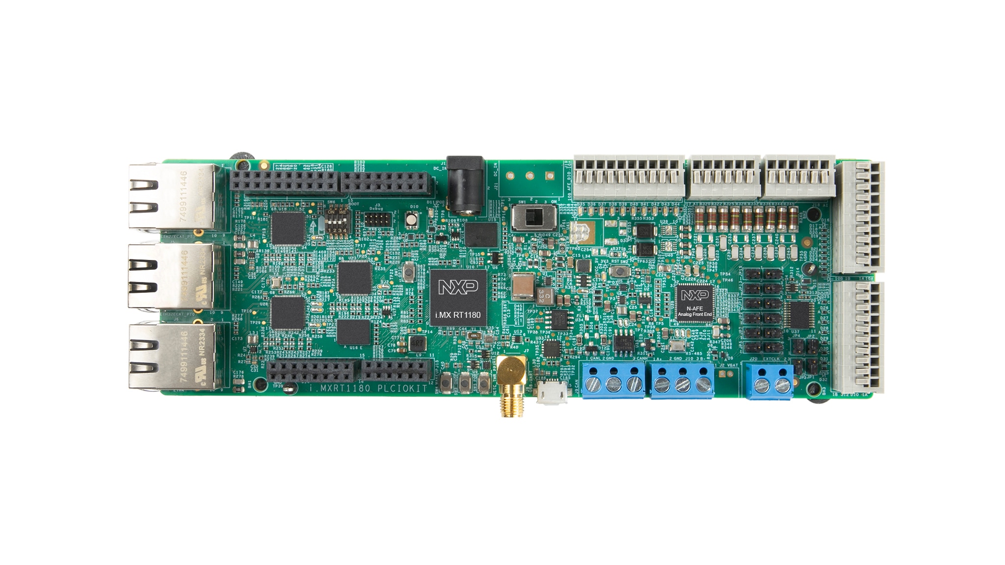
The RIOP is designed for developers seeking multi-protocol, industrial real-time Ethernet communication support. The platform integrates the i.MX RT1180 MCU and NAFE13388 analog front-end (AFE) into a fully tested, modular and expandable system. This solution accelerates time-to-market for developers of remote I/O and digital and analog I/O modules.
The platform comes with example applications showcasing the enabled industrial protocols:
- Demo (out-of-the-box experience): Uses Network Controller (NETC) over Ethernet to communicate with FreeMASTER on a PC, providing an intuitive out-of-box experience
- Ethernet for Control Automation Technology Sample Application (ECAT Sample Application): Demonstrates the NXP implementation of the EtherCAT protocol by communicating with a TwinCAT-driven soft-programmable logic controller (soft-PLC) application on a PC
3.1 Board Features
- Complete reference platform for the i.MX RT1180 and NAFE13388
- Support for industrial communication protocols
- Eight configurable analog input AFE pins
- Ten configurable digital I/O AFE pins
- Seven digital input MCU pins
- Eight digital output MCU pins
- Three Ethernet ports
- USB interface for connecting the host PC and powering the board
- External power supply option
4. Configure Hardware
4.1 Configure Hardware
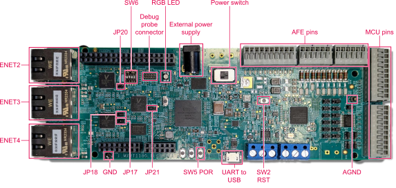
Note: The board can be powered by a 24 V or 5 V adapter through the external power supply port, or via a micro-USB cable connected to the Universal Asynchronous Receiver-Transmitter (UART)-to-USB port. When the micro-USB port is used, the power switch will not be used. You can use both an external power supply and a micro-USB cable simultaneously.
Before running the application, perform the following steps:
-
Configure the
SW6switch to set the boot mode (each pin can be set to ON [up] or OFF [down]), then set the positions to: 1: OFF, 2: ON, 3: OFF, 4: OFF - Connect
JP17andJP18to position 2-3 (the left-most and the middle pin, as they are numbered 3-2-1) - Connect external power supply of 24 V to the programmable logic controller input/output (PLCIO) board
- Power on the board
- Connect Ethernet port 4 (
ENET4) to your PC with an Ethernet cable - Connect a micro-USB cable between the board and the PC
5. Run the Application
5.1 Connect FreeMASTER to the Board
To connect the FreeMASTER tool with the board, perform the following steps:
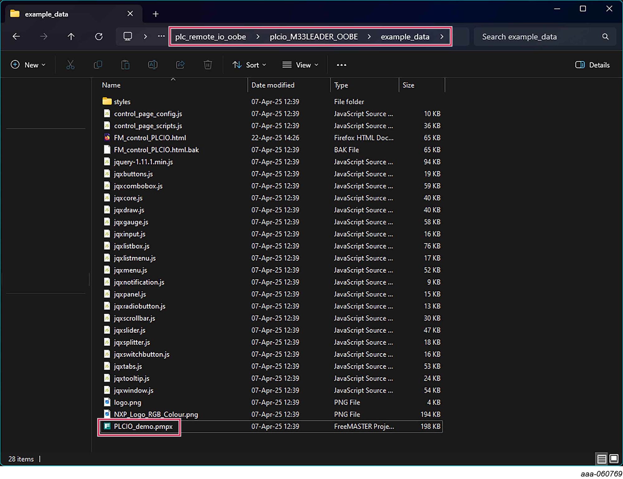
- Open the folder with the downloaded RIOP software package, then navigate to "riop_M33LEADER_DEMO/example_data" and open "RIOP_demo.pmpx"
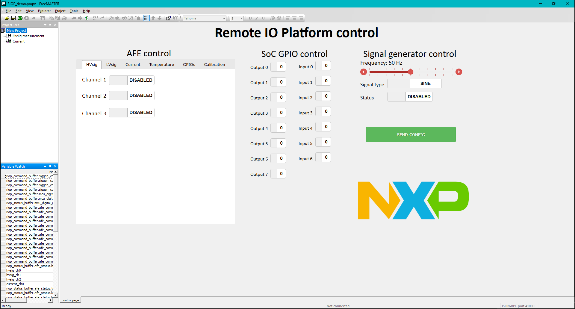
- The FreeMASTER application will open
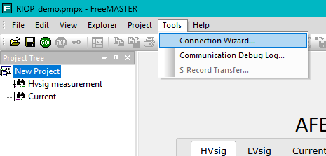
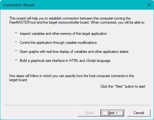
- Go to "Tools" → "Connection Wizard"
- Click "Next"
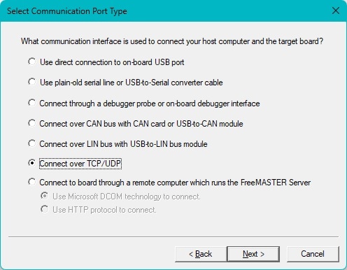
- Select the "Connect over TCP/UDP" option, then click "Next"
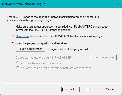
- Click "Plug-in Configuration"
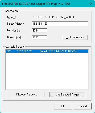
- Click "Discover Targets" then select an available target and press "Use Selected Target", then click "OK"
- Click "Finish"
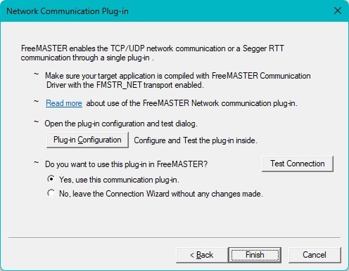
FreeMASTER is now connected to the board so the application can be used.
5.2 Test the Connection
To test the connection, measure the external voltage signal by performing the following steps:
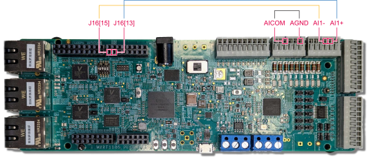
- Connect the blue wire between
J16[13]andAI1+(5th pin from the left) - Connect the yellow wire between
J16[15]andAI1-(4th pin from the left) - Connect the black wire between analog input common (
AICOM) (3rd pin from the left) and analog ground (AGND) (6th pin from the left) - Enable a signal generator using the FreeMASTER application
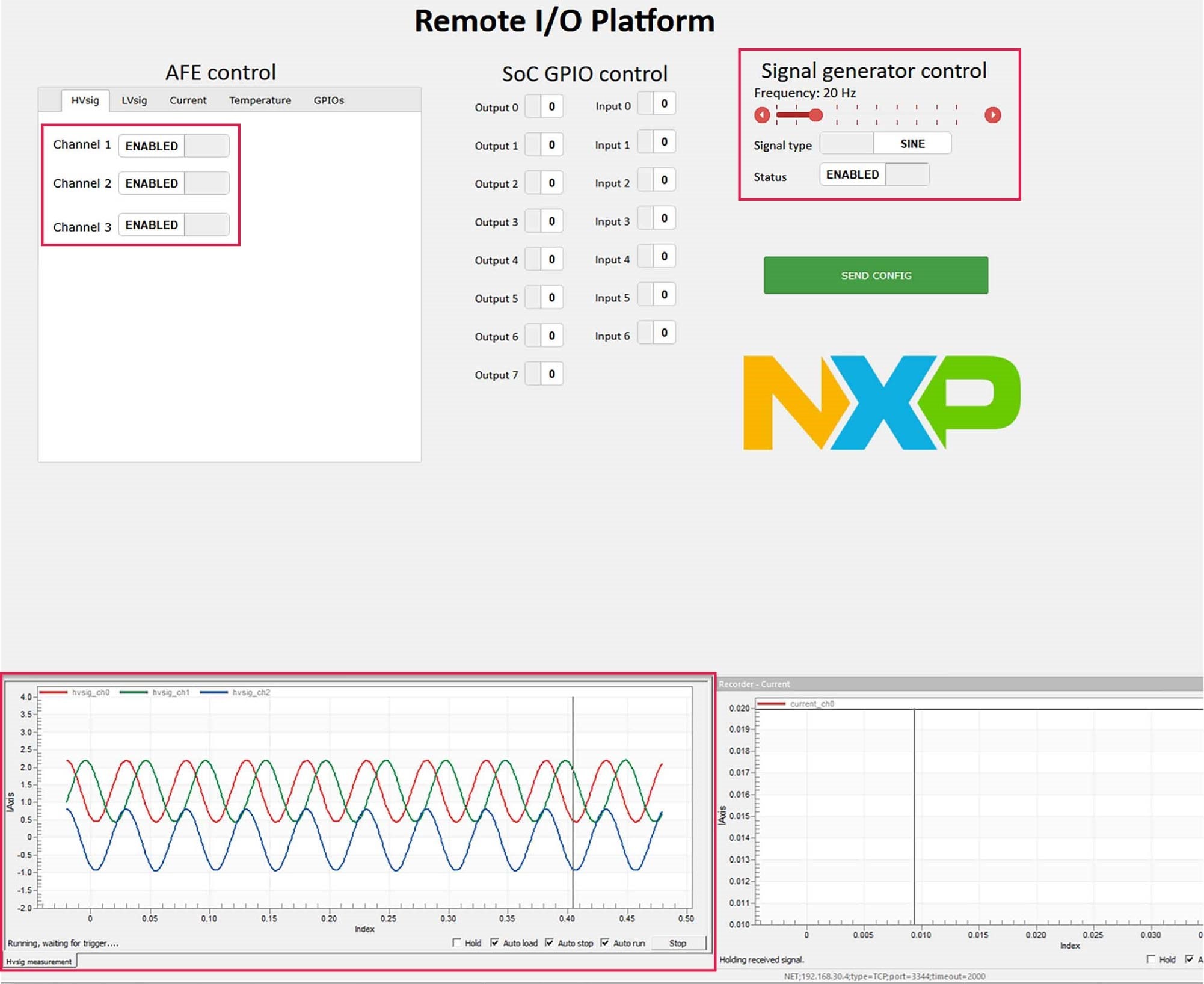
- In the high-voltage signal ("HVsig") tab, enable one or more channels
- Press the "SEND CONFIG" button
- Check the signal waveform in the recorder – "HVsig" window
- Double-click on the "Hvsig measurement" button in the Project tree to switch to the "HVsig" view (alternatively, you may right-click on the "Hvsig measurement" button and choose "New window" to show it like in Figure 13)
When "SINE" is enabled, channels 1 and 3 are offset from each other and channel 2 is the difference between the other two waves (bur when "SAWTOOTH" is enabled, there are no offsets between the channels and channel 2 shows 0).
Design Resources
Board Documents
Chip Documents
Additional References
Support
Forums
Connect with other engineers and get expert advice on designing with the PLCIOKIT on one of our community sites.