Getting Started with the OM-UBX100-001 Radio Evaluation Board
このドキュメントの内容
-
Out of the Box
-
Get Hardware
-
Install Software
-
Configure the Hardware
サインイン 進行状況を保存するには アカウントをお持ちでない方 アカウントを作成する。
お客様の OM-UBX100/001
1. Out of the Box
The NXP analog product development boards provide an easy-to-use platform for evaluating NXP products. The boards support a range of analog, mixed-signal and power solutions. They incorporate monolithic integrated circuits and system-in-package devices that use proven high-volume technology. NXP products offer longer battery life, a smaller form factor, reduced component counts, lower cost and improved performance in powering state-of-the-art systems.
This page will guide you through the process of setting up and using the OM-UBX100-001 radio evaluation board.
1.1 Kit Contents
The OM-UBX100-001 radio evaluation board kit includes the following:
- Assembled and tested OM-UBX100-001 evaluation board in an antistatic bag
- RF shield can (assembled on board)
- Standard pin headers for the
J6andJ7board headers - Packing list with a QR code linking to the OM-UBX100-001 product page
1.2 Additional Hardware
In addition to the kit contents, the following hardware is necessary when working with this board.
- FRDM-MCX MCU development board
1.3 Minimum System Requirements
This radio evaluation board requires meeting the following for operation:
- PC with Windows 10 or higher
- USB port (either 3.0, 2.0 or 1.1 compatible)
-
An FRDM-MCX MCU development board
- See Supported hardware for details
-
UBX100 FreeMASTER evaluation GUI sample application
- See the Tool interface (GUI) description for details
- USB cable for power and data connection between the PC and FRDM-MCX board
For basic RF operation, it is recommended to use two sets of FRDM-MCX and OM-UBX100-001 boards. For evaluation of the supported protocols and their stacks, a receiver or sniffer could be required. Different third-party products are available for this purpose. Selection of these products and their use is left to the discretion of the reader and is out of the scope of this document.
2. Get Hardware
2.1 Kit Overview
The OM-UBX100-001 is a mikroBUS add-on board ready for evaluation of the UBX100. The board hosts a 55.2 MHz TCXO, providing the main clock and a stable source over the device lifetime. The OM-UBX100-001 also comes with a wideband matching that allows operation across the 868 MHz to 928 MHz frequencies. The RF matching provides a conducted output power of up to 14 dBm across the frequency range.
The IC is preprogrammed with firmware that allows operation of the device through SPI commands using a proprietary protocol from NXP. In addition, the UBX100 contains a bootloader in ROM memory enabling in-the-field updates of its firmware.
2.2 Board Features
Table 1 describes the features of the OM-UBX100-001 board.
| Board feature | Description |
|---|---|
| UBX100 radio |
The UBX100 is a sub-GHz radio transceiver.
|
| Power supply |
The board is typically powered as follows:
|
| Clock | The board has a 55.2 MHz TCXO that provides the reference clock for the UBX100. |
| RF matching |
Dedicated matching circuit for the TX and RX paths. The UBX100 has an internal TRX switch used to tie both circuits to the antenna path.
|
| Antenna connector |
|
| Connectors |
Connectors for the following features are included:
|
| Other - RF path selection |
RX pin selection through 0 Ω resistor in a three-terminal resistor (R5). Pin RF_IN_B is the default. To verify compatibility or changes, consult the UBX100 SDK software release note.
|
| Other - RF shield |
Three ground mounting clips for an RF Shield are provided on the board. The shield is not assembled by default. The board was used without the shield during compliance testing. It is recommended to use the boards without the shield. |
| Type approval | The board has been tested for compliance with the Radio Equipment Directive 2014/53/EU. |
| PCB dimensions | 42.9 mm x 25.4 mm – Compliant with mikroBUS M size add-on board. |
| Orderable part number | OM-UBX100-001 |
2.3 Kit Featured Components
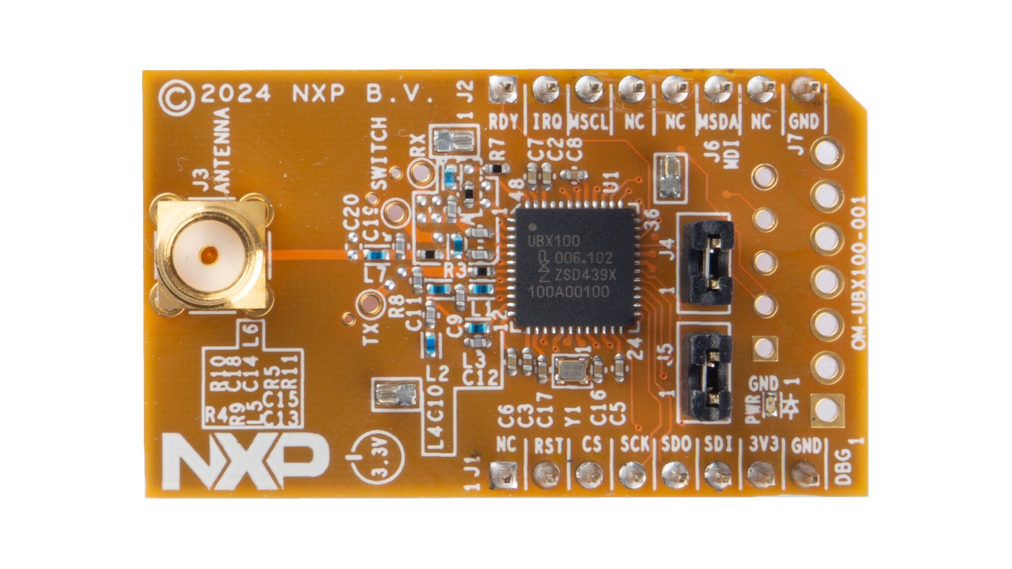
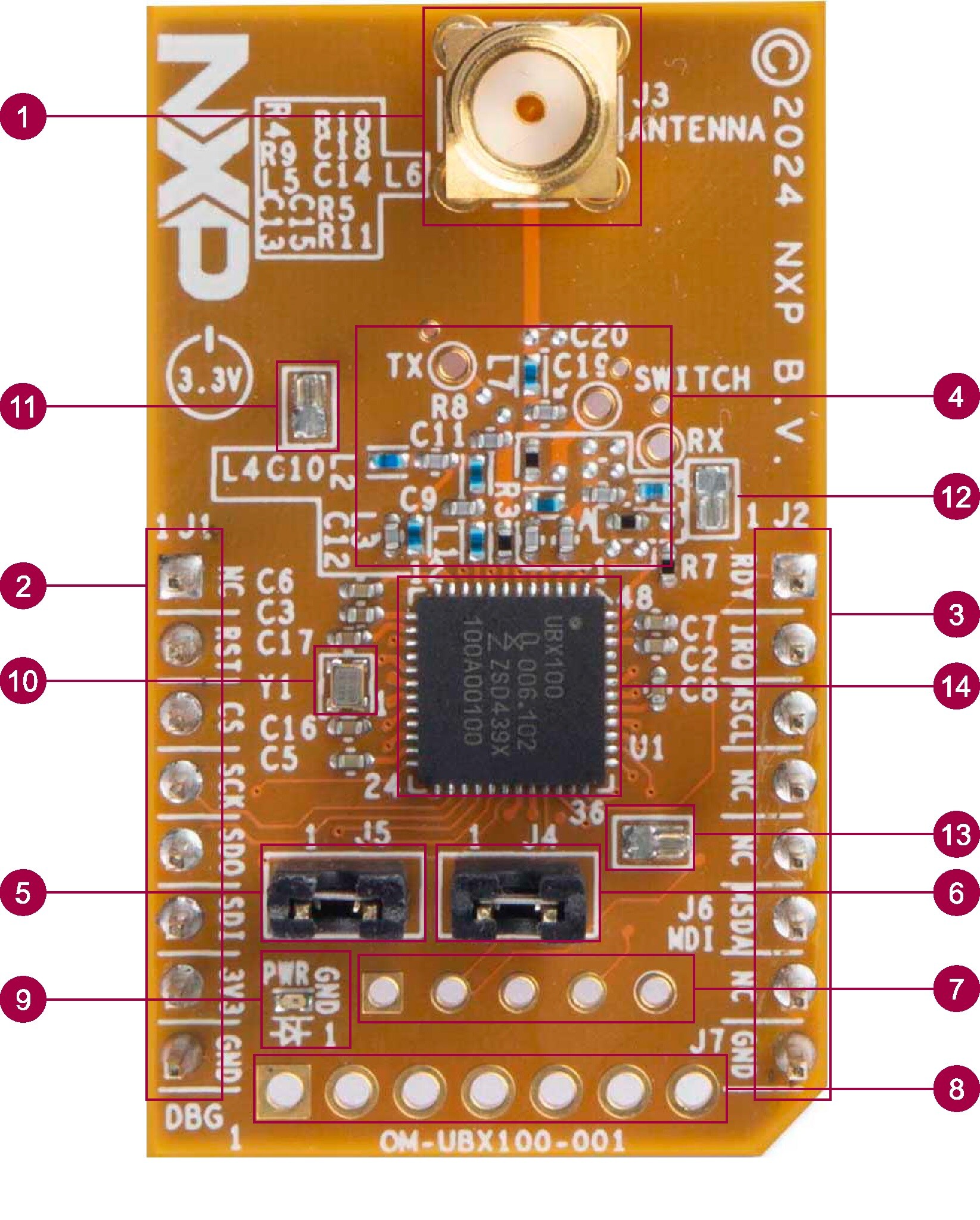
Figure 1 highlights the main functional elements in the OM-UBX100-001 radio evaluation board. The physical appearance of the board could vary slightly from the final product assembly.
| Number | Name | Description |
|---|---|---|
| 1 | Antenna connector | SMA connector for an external antenna. |
| 2, 3 | mikroBUS add-on connector | Provide connectivity to FRDM-MCX boards with mikroBUS socket. |
| 4 | RF matching and RF test points |
Wideband TX and RX matching for the frequency range of 868 MHz to 928 MHz Test points marked as TX, SWITCH and RX. |
| 5 | Current measurement jumper | To measure the current consumption of the board (except for power LED). |
| 6 | MDI supply jumper | Allow the MDI connector to power the device. |
| 7 | MDI connector | Monitor and Debug Interface. |
| 8 | GPIO debug connector | Expose the P10, P11, P20, P21, P22 and P23 special purpose GPIOs of the UBX100. |
| 9 | Power LED | Indicates if the board is powered. |
| 10 | TCXO | 55.2 MHz clock source for the UBX100. |
| 11, 12, 13 | RF Shield Can mounting clips | Mounting points for the RF Shield Can. |
| 14 | RF Shield can mounting clips | RF Shield can be used to improve. |
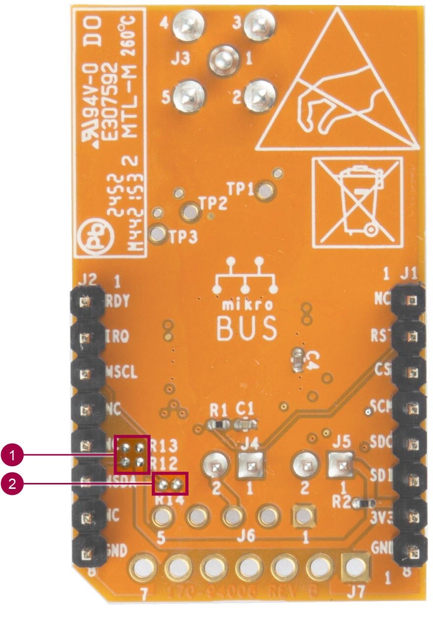
| Number | Name | Description |
|---|---|---|
| 1 | MDI connector resistors | 0 Ω resistors to enable routing of the MDI signals to the mikroBUS header. |
| 2 | MDI MSDA pull-up | Pull-up resistor for the MSDA MDI signal. |
2.4 Supported Hardware
The UBX100 requires a host controller for operation. For this purpose, an MCU from the MCX family can be used. Software support is offered for the following NXP evaluation board:
- FRDM-MCXN947
While compatibility could be possible through other platforms, dedicated examples are available only for the listed board. NXP also recommends consulting the UBX100 and OM-UBX100-001 product pages for updates on supported platforms and new software packages.
3. Install Software
3.1 Install Software
The OM-UBX100-001 board is designed to work together with an FRDM-MCX development board equipped with a mikroBUS socket. Details on hardware compatibility can be seen in Supported hardware.
The OM-UBX100-001 boards come preprogrammed with the necessary firmware for operation. When new firmware is released, updates are possible through the UBX100 integrated bootloader. A sample application for this purpose can be found in the UBX100 and OM-UBX100-001 product pages.
For the FRDM-MCX board, the UBX100 FreeMASTER evaluation GUI application must be downloaded and flashed to the board. This application is the main example for evaluation of the FRDM-MCX and OM-UBX100-001 boards. The GUI provides a FreeMASTER-based interface to control the OM-UBX100-001 board for simple RF evaluation. A FreeMASTER Lite installation is required to operate this example. Visit FreeMASTER to download it and for installation instructions.
The UBX100 FreeMASTER evaluation GUI example package contains:
- The MCUXpresso project for the FRDM-MCXN947 board
- The binary file of the project in HEX format, ready for flashing to the FRDM board
- The GUI launcher
To flash the FRDM-MCXN947 board, the included MCUXpresso project can be compiled and flashed. Optionally, the provided HEX file can be programmed directly to the board using the MCUXpresso tool LinkFlash.
Software support for the FRDM-MCX boards, including sample applications and firmware updates for the UBX100, can be downloaded from the UBX100 or OM-UBX100-001 pages.
4. Configure the Hardware
4.1 Configure the Hardware
The basic list of materials required to evaluate the OM-UBX100-001 board are listed below.
- 1x OM-UBX100-001 board
- 1x SMA antenna (50 Ω impedance, compatible with the frequency band of 868 MHz to 928 MHz)
-
1x FRDM-MCX development board
- See Supported hardware for compatible host MCU boards
- It is assumed that the FRDM-MCX board has been previously flashed with the UBX100 FreeMASTER evaluation GUI as described in Section 3
- 1x USB-A to USB-C cable
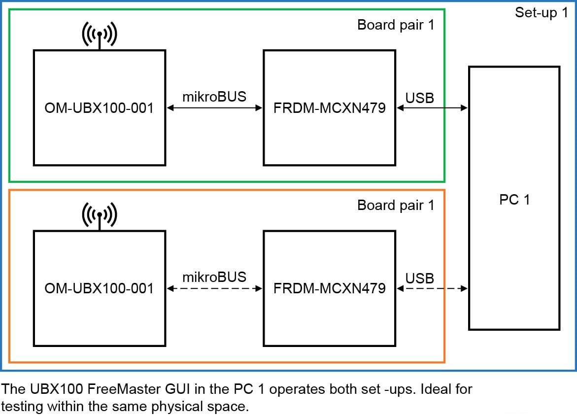
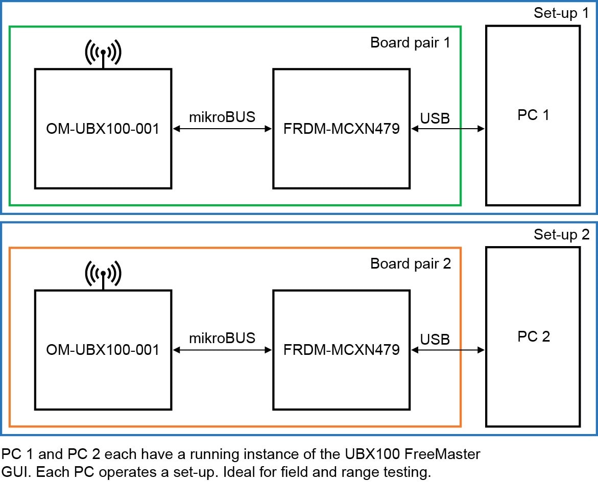
The UBX100 FreeMASTER evaluation GUI allows testing of up to two FRDM-MCXN and OM-UBX100-001 board pairs with the same host PC. It is also possible to use two individual PCs, each operating a different board pair. This configuration is desirable when using the range testing feature of the application. Figure 3 and Figure 4 show a simplified diagram of the different set-up options.
The following steps describe the set up process of the boards for testing. The FRDM-MCXN947 is used as a reference for the host microcontroller board.
- Configure the power supply jumpers of the OM-UBX100-001 board
- Populate
J5. For current profiling,J5can be removed and a DMM or energy profiler can be connected instead. - Optional: Remove
J4
- Populate
- Connect an antenna to the SMA connector
- Failure to attach an antenna could lead to unexpected behavior during RF operation due to load mismatch. For example, increased current consumption
- Connect the OM-UBX100-001 board to the mikroBUS socket on the FRDM-MCXN947
- Ensure that the mikroBUS socket silkscreen notch aligns with the OM-UBX100-001 notch
- Connect the FRDM-MCXN947 board to a host computer using the USB-A to USB-C cable
- Use the USB-C connector of the FRDM board with the MCU-Link label
- The FRDM-MCXN947 is now powered. The device also supplies the OM-UBX100-001 board through the 3V3 pin in the mikroBUS socket
- The green LED in the OM-UBX100-001 board lights up, indicating it is powered
- The set up is ready to be used together with the UBX100 FreeMASTER evaluation GUI
Design Resources
Board Information
Additional Resources
In addition to our UBX100, Sub-GHz Wireless M-Bus Solution page, you may also want to visit:
Applications: