EVBMA7118DTのスタート・ガイド
このドキュメントの内容
-
パッケージの内容
-
ハードウェアの入手
-
ハードウェアの構成
サインイン 進行状況を保存するには アカウントをお持ちでない方 アカウントを作成する。
お客様の 絶縁型デイジー・チェーンを備えたBMA7118評価ボード
1. パッケージの内容
NXPのアナログ製品開発ボードは、NXP製品の評価を目的とした使いやすいプラットフォームです。
さまざまなアナログ・ソリューション、ミックスド・シグナル・ソリューション、パワー・ソリューションに対応しています。実績のある大容量テクノロジを使用したモノリシック集積回路 (IC) およびシステム・イン・パッケージ (SiP) デバイスを搭載しています。NXP製品は、最先端システムへの電源供給において、より長いバッテリー寿命、より小さいフォーム・ファクタ、より少ない部品数、より低いコスト、より優れたパフォーマンスを実現します。
このページでは、EVBMA7118DTボードをセットアップして使用する手順について説明します。
1.1 キットの内容と同梱物一覧
EVBMA7118DTには以下のものが含まれています。
- 組立て済み/テスト済みのEVBMA7118DTボード(静電気防止バッグ入り)
- トランスポート・プロトコル・リンク (TPL) ケーブル
- バッテリー・エミュレータ接続ケーブル
2. ハードウェアの入手
2.1 ボードの特長
このボードは、抵抗分圧回路を実装することでセル・エミュレータを使用せずにアナログ・フロントエンド (AFE) の改良を可能にし、次の機能も備えています。
- BATT-18EMULATORまたは実際のセルに接続するオプション
- セル0を外部刺激に接続するオプション
- 汎用入力/出力 (GPIO) ピンへの簡単なアクセス
- 操作モード・インジケータ
- コンポーネント・アセンブリを上面のみに実装
- コンパクトなデザイン
- 最小限の部品表 (BOM)
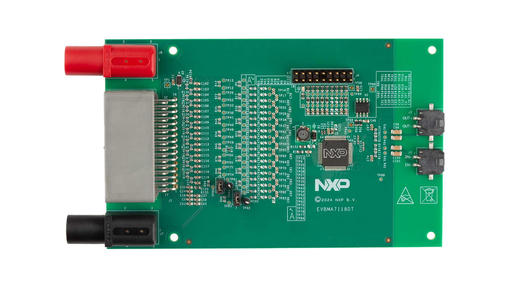
2.2 ボードの説明
EVBMA7118DTは、1つのBMA7118を使用したバッテリー・モニタ評価ボードです。BMA7118は、18セルのAFE集積回路 (IC) です。ボードには、BMA7118を操作するために必要な補助コンポーネントが含まれています。
EVBMA7118DTには、DCラボ電源から電力を供給できます。または、ボードをBATT-18EMULATORまたは実際のバッテリー・セルに接続することもできます。

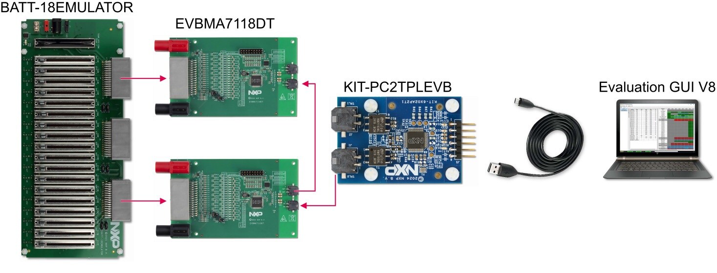
3. ハードウェアの構成
図2に、セットアップの全体を示します。このセットアップでは、BATT-18EMULATORを使用して、2つのEVBMA7118DTボードのセル電圧を供給およびエミュレートします。KIT-PC2TPLEVBは、通常のPCとの通信が可能です。評価用グラフィカル・ユーザー・インターフェース (GUI) は、測定された電圧を表示し、BMA7118デバイスとの対話を可能にします。評価の範囲に応じて、異なるコンポーネント(実際のバッテリー・セルまたは異なるTPL通信源など)を使用するよう評価システムを変更することができます。
設計・リソース
その他の参考情報
NXPのEVBMA7118DTのページに加えて、BMA7118、18チャネル・リチウムイオン・バッテリー・セル・コントローラICもご覧ください。