BRKTSTBAPx7250評価ボードのスタート・ガイド
このドキュメントの内容
-
パッケージの内容
-
ハードウェアの入手
-
ソフトウェア・ツールのインストールと構成
-
ハードウェアの構成
サインイン 進行状況を保存するには アカウントをお持ちでない方 アカウントを作成する。
お客様の BRKTSTBAPx7250
1. パッケージの内容
NXPのアナログ製品開発ボードは、NXP製品の評価を目的とした使いやすいプラットフォームです。さまざまなアナログ・ソリューション、ミックスド・シグナル・ソリューション、パワー・ソリューションに対応しています。実績のある大容量テクノロジを使用したモノリシック集積回路およびシステム・イン・パッケージ (SiP) デバイスを搭載しています。NXP製品は、最先端システムへの電源供給において、より長いバッテリー寿命、より小さいフォーム・ファクタ、より少ない部品数、より低いコスト、より優れたパフォーマンスを実現します。
このページでは、BRKTSTBAPx7250ボードをセットアップして使用する手順について説明します。
1.1 キットの内容と同梱物一覧
BRKTSTBAPx7250は、単独のボードとして提供されます。ボックスには以下のものが含まれています。
- 組立て済み/テスト済みの評価ボード(静電気防止バッグ入り)
1.2 追加ハードウェア
BRKTSTBAPx7250は、任意のNXP MCUボードと組み合わせることができますが、FRDM-KE15Z MCUおよびFRDMK64F Freedomボードを対象とした評価用のサンプル・プロジェクトが用意されています。
- FRDM7X-INTERFACEボード
- FRDM-KE15Z MCU Freedomボード:I²Cおよびアナログ・オプション用
- FRDM-K64F MCUボード:SPIオプション用
- ソフトウェアがインストールされたWindows PCも必要です
1.3 前提条件
サンプルのデモ・ソフトウェアを使用するには、3枚のボードをすべて接続する必要があります。
1.4 静電気処理要件
感電および火災の危険
このデバイスは静電気放電 (ESD) に敏感です。したがって、輸送および取り扱いの際には注意が必要です。ハードウェアの開梱または取り扱い前には、グランド・ストラップを使用するか、PCケースまたはその他の接地された箇所に触れる必要があります。
1.5 最小システム要件
この評価ボードには以下が必要です。
- Windows 10 PCワークステーション
- FRDM7X-INTERFACEボード
- FRDM-KE15Z MCU Freedomボード:I²Cおよびアナログ・オプション用
- FRDM-K64F MCUボード:SPIオプション用
2. ハードウェアの入手
2.1 ボードの特長
- 圧力/温度範囲とパッケージ
- 絶対圧力範囲:20~250 kPa(BRKFXPS7XXX-PCBボードを使用して他の圧力オプションも利用可能)
- 動作温度範囲:–40°C~130°C
- 鉛フリー、16ピンHQFN、4 mm x 4 mm x 1.98 mmパッケージ
- I²C互換シリアル・インターフェース
- フォロワー・モード動作
- 標準モード、ファスト・モード、およびファストモード・プラスのサポート
- 32ビットSPI互換シリアル・インターフェース
- センサ・データ送信コマンド
- 12ビットの絶対圧データ
- 8ビットの温度データ
- 2ビットの基本ステータスおよび2ビットの詳細ステータス・フィールド
- 3、4、または8ビットの設定可能なCRC
- デジタル・セルフテスト
2.2 ボードの説明
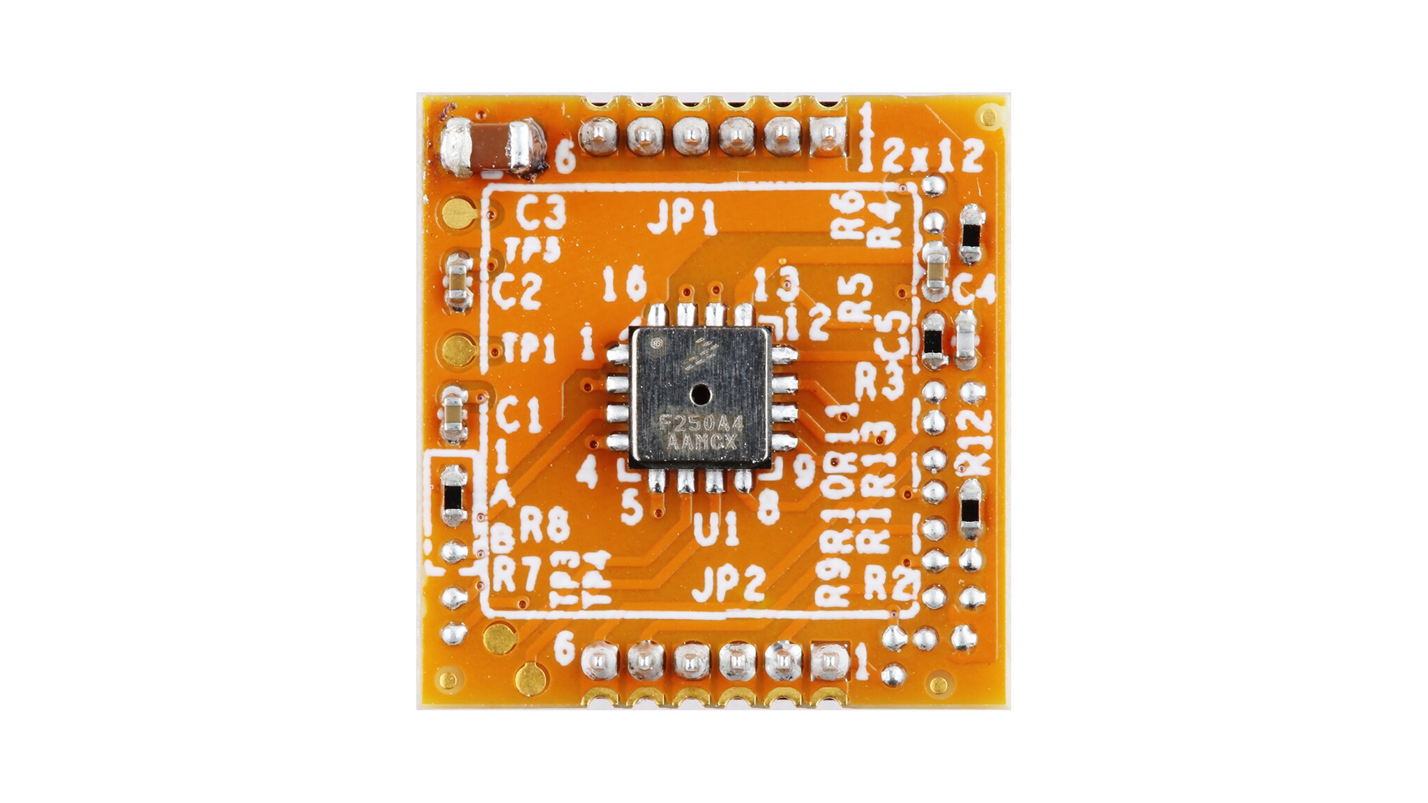
BRKTSTBAPx7250ブレークアウト・ボードは、完全統合型の高性能絶対気圧 (BAP) センサであるFXPS7250を搭載しています。このセンサは、コンパクトな静電容量式MEMSデバイスにデジタル集積回路を組み合わせ、完全に較正されたデジタル出力を生成します。
BRKTSTBAPx7250評価ボードは、NXPのFreedom MCUボードにArduinoヘッダを介して簡単に接続してエミュレーションを行えますが、Arduinoに対応するにはFRDM7X-INTERFACEボードが必要です。以下のボードをお勧めします。
- FRDM7X-INTERFACE
- FRDM-KE15Z – アナログおよびII²C互換ブレークアウト・ボード用
- FRDM-K64F – SPI互換ブレークアウト・ボード用
2.3 ボードのコンポーネント
BRKTSTBAPx7250ボードの概要。
BRKTSTBAPx7250は、FXPS7250DI4S絶対圧力センサ、FXPS7250DS4Sデジタル絶対気圧 (DBAP) センサ、FXPS7250A4Sアナログ・マニホールド絶対圧 (AMAP) センサを迅速に評価するために必要なヘッダ、ジャンパ、テスト信号をすべて備えた、3枚の評価ボードのセットです。
さらに、FRDM7X-INTERFACEボードは、3種類すべてのBRKTSTBAPx7250を、MCUXpressoプロジェクト・ベースのソフトウェアが提供される任意のNXP Freedom MCUと組み合わせることができる共通のインターフェースを提供します。
また、他の圧力範囲に対応するために、ブランクPCBであるBRKFXPS7XXX-PCBも提供されています。ユーザーは、必要なインターフェース(アナログ、SPI、またはI²C)に基づくNXP提供の回路図を使用して、選択した圧力センサと適切なパッシブ部品をボードに取り付けることができます。
| 番号 | 説明 |
|---|---|
| U1 | FXPS7250A4ST1気圧センサ (BAP)、アナログ出力 |
| U1 | FXPS7250DI4ST1気圧センサ (BAP)、I²Cプロトコル |
| U1 | FXPS7250DS4ST1気圧センサ (BAP)、SPIプロトコル |
3. ソフトウェア・ツールのインストールと構成
3.1 ソフトウェア・ツールのインストールと構成
NXPでは、迅速な評価とプロトタイプ作成のためのコンポーネント・ライブラリ・ソフトウェア・サンプルを提供しています。これらのデモ・プロジェクトは、FRDM-KE15Z(アナログおよびI²Cオプション)およびFRDM-K64F(SPIオプション)を対象としており、NXPセンサのセンサ・ドライバのリンクから設計リソース、ソフトウェア、BSP、ドライバ、ミドルウェアにアクセスできます。サンプルとともにFXPS7xxxセンサ・ドライバをダウンロードするには、「ダウンロード」セクションまでスクロールしてください。
4. ハードウェアの構成
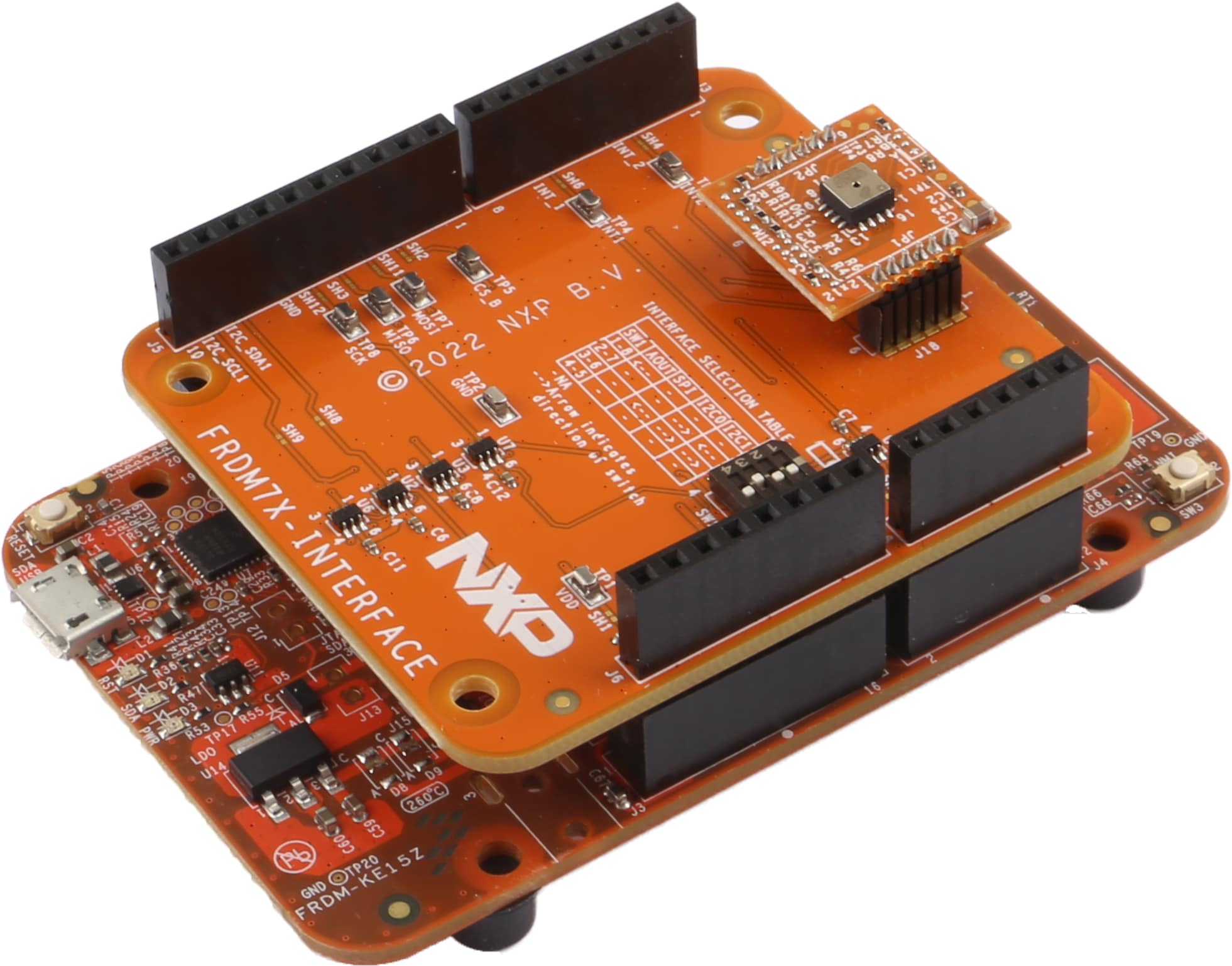
4.1 ハードウェアの構成
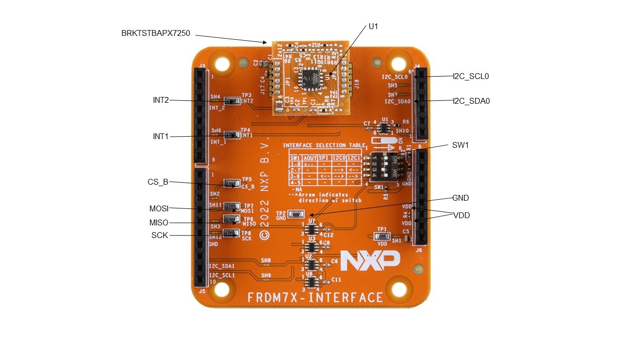
図1に、BRKTSTBAPx7250開発ボード、FRDM7X-INTERFACEボード、FRDM-KE15Z MCUボードを含むハードウェア構成を示します。評価キットはUSBケーブルでWindows PCに接続します。
開発ボードの設定作業として必要なのは、FRDM7X-INTERFACEボード上の4つのSW1位置の設定のみです。4つのSW1位置は、対応するBRKTSTBAPx7250ブレークアウト・ボードのプロトコル(アナログ、I²C、またはSPI)に応じて設定されます。
表2に、開発ボードの出力プロトコルに対応する各スイッチの位置を示し、これらは次のように定義されています。
SW1:0/1位置
- 0位置は右側(信号Low)
- 1位置は左側(信号High)
- ‒ Don’t care
| SW1 | アナログ | SPI | I²C |
|---|---|---|---|
| 1 | ← | ← | — |
| 2 | — | ← | → |
| 3 | — | ← | → |
| 4 | — | — | — |
設計・リソース
ボード情報
- BRKTSTBAPA7250S設計ファイル
- BRKTSTBAPDI7250設計ファイル
- BRKTSTBAPDS7250設計ファイル
- BRKFXPS7XXX-PCB設計ファイル
- SPF-88891、BRKTSTBAPA7250S回路図
- SPF-46092、BRKTSTBAPDS7250回路図
- SPF-46091、BRKTSTBAPDI7250回路図
- SPF-87708、BRKFXPS7XXX-PCB回路図
- UM11863、BRKTSTBAPx7250評価ボード・ユーザー・マニュアル
- UM11515、コンポーネント・ライブラリ – スタート・ガイド/ユーザー・マニュアル
- UM11516、コンポーネント・ライブラリ – センサ・ドライバ・コンポーネント