KW47-LOCのスタート・ガイド
サインイン 進行状況を保存するには アカウントをお持ちでない方 アカウントを作成する。
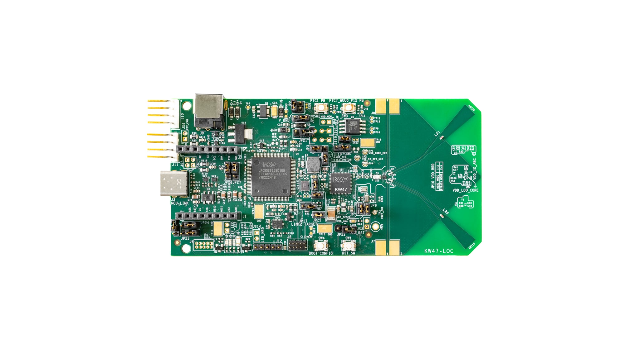
お客様の KW47 Bluetoothチャネル・サウンディングMCU用位置特定ボード
1. 接続
ボードを実際に使ってみましょう。ショート・ビデオで手順を視聴するか、以下に記載された詳細な手順を参考にして、次の作業を進めてください。
1.1 ボードの概要
KW47-LOCボードには、ワイヤレス位置特定のデモが事前にプログラム済みです。これは、開梱したデバイスが正常に動作することをその場で検証するための動作確認用に使用できます。

2. ソフトウェアの入手
2.1 ツールチェーンをインストールする
NXPは、MCUXpresso for Visual Studio (VS) Code というツールチェーンを提供しています。下のボタンをクリックして、MCUXpresso for VS Code v25.09以降をダウンロードしてください。
MCUXpressoチュートリアルに従って、ホストPCにVS Codeをインストールする方法を学びましょう。
2.2 MCUXpresso SDKですぐに設計を開始する
NXPの拡張機能では、VS Codeのワークスペースにソフトウェア・リポジトリを追加するためのツールが用意されています。このソフトウェア・リポジトリは、次の3つのソースから追加できます。
- GitのリモートURL
- NXPのMCUXpressoアーカイブ・ファイル
- 既存のGitフォルダ
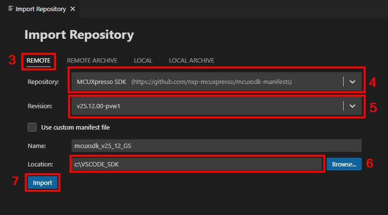
このセクションでは、Gitのリモート・リポジトリ・オプションを使用してMCUXpresso SDKをインポートする方法を説明します。この方法でリポジトリをインポートするには、以下の手順に従ってください。
- MCUXpresso拡張機能のアイコンをクリックします
- [QUICKSTART PANEL(クイックスタート・パネル)]タブをクリックし、次に[Import Repository(リポジトリのインポート)]ボタンをクリックします。このボタンをクリックすると、新しいインポート・ウィンドウが表示されます
- [Remote(リモート)]オプションを選択して、提供されているSDKファイルをインポートします
- [Repository(リポジトリ)]オプションの矢印ボタンをクリックして参照し、[MCUXpresso SDK]オプションを検索します
- [Revision(リビジョン)]の矢印ボタンをクリックし、バージョン[v25.09.00]以降を検索します
- [Location(保存先)]フォルダの[Browse(参照)]をクリックし、SDKの共通の保存先となるフォルダを選択します
- 新しいSDKの名前を入力します
- [Import(インポート)]ボタンをクリックして、インストールが完了するのを待ちます

2.3 MCUXpresso Config Tools
MCUXpresso Config Toolsは、ユーザーがMCUXpresso SDKプロジェクトを新規に作成するためのツールの統合スイートであり、カスタム・ボード・サポート用の初期化Cコードを生成するためのピン・ツールとクロック・ツールも備えています。このツールは、MCUXpresso統合開発環境 (IDE) の一部として完全に統合されていますが、(別のIDEを使用する場合には)独立したツールとしても使用できます。
以下の[MCUXpresso Config Toolsを入手する]ボタンをクリックして、インストーラを入手してください。

2.4 プログラミング・ツールとプロビジョニング・ツール
MCUXpressoセキュア・プロビジョニング (SEC) ツールは、NXPのマイクロコントローラ・ユニット (MCU) デバイスでブート可能な実行ファイルを簡単に生成およびプロビジョニングできる、グラフィカル・ユーザー・インターフェース (GUI) ベースのアプリケーションです。このツールは、生産段階におけるNXPのマイクロコントローラでのセキュア・プログラミングとデバイス・プロビジョニングをサポートします。いずれのユーザーも、試験運用および量産に向けてMCUXpresso SECツールから始めることをお勧めします。
ツールをダウンロードすると、[Help(ヘルプ)]タブの下にユーザー・ガイドが表示されます。さらに、「プロセッサ固有のワークフロー」の章に記載されている、ボードに関する指示に従ってください。

注:NXPでは、より柔軟な設定のカスタマイズを必要とする上級ユーザー向けに、カスタムまたはパートナーのプログラミング・ツールを操作する際に役立つコマンドライン・ツールも提供しています。セキュア・プロビジョニング・ソフトウェア・開発キット (SPSDK) はオープンソースの開発キットであり、そのソース・コードはGitHubおよびPyPIでリリースされています。
3. ビルドと実行
次の手順では、Arm® Cortex®-M33アプリケーション向けにMCUXpresso for VS Code拡張機能を使用したワイヤレス位置特定デモ・アプリケーションについて説明します。VS CodeのMCUXpresso拡張機能のインストール手順およびKWシリーズのSDKについては、このスタート・ガイドの「ソフトウェアの入手」セクションを参照してください。
3.1 NBUファームウェアのアップデート
ワイヤレス・デモを実行する前に、SDKのバージョンに応じて狭帯域ユニット(NBU)ファームウェアをアップデートする必要があります。
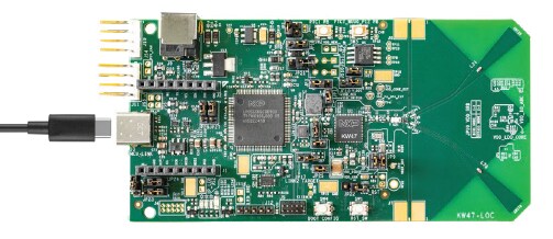
- USB Type-Cケーブルを使用して、KW47-LOCボードをPCに接続します
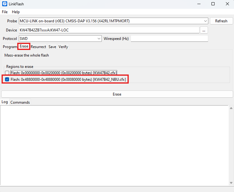
- セクション 2.1でインストールしたLinkFlashツールを開きます(このツールはLinkServerのコンポーネントに付属しています。このツールのデフォルトのパスは「
C:\nxp\LinkServer_XX.XX.XX\LinkFlash.exe」です) - [Probe(プローブ)]フィールドで、ツールによってボードが認識されていることを確認します(認識されていない場合は、[Refresh(再読み込み)]をクリックします)
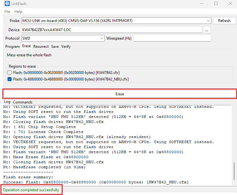
- [Erase(消去)]タブに移動したら、NBUメモリ領域のチェックボックスをクリックして選択します
- [Erase(消去)]ボタンをクリックしたら、正常に処理されたことをウィンドウの下部にあるメッセージで確認してください
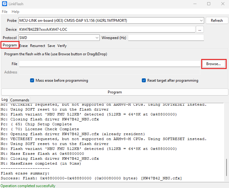
- [Program(プログラム)]タブに戻り、[Browse(参照)]ボタンをクリックしてNBUファームウェアのバイナリ・ファイルを探します
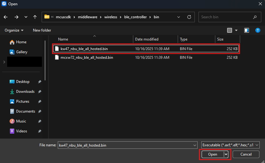
- セクション 2.2でSDKをインストールしたディレクトリにアクセスします。NBUファイルのパスは、「
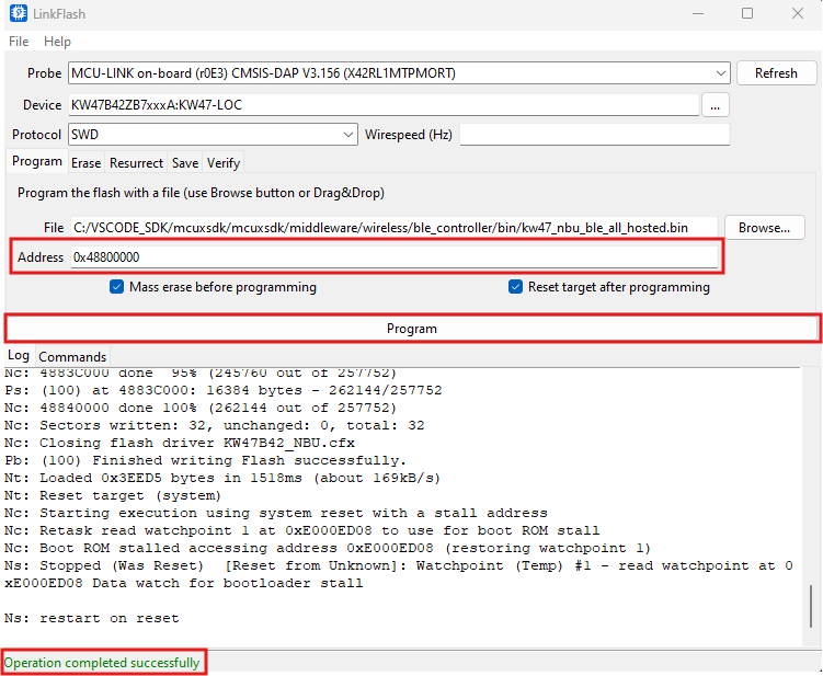
{your_SDK_path}\mcuxsdk\middleware\wireless\ble_controller\bin\kw47_nbu_ble_all_hosted.bin」です。その後、[Open(開く)]をクリックします - [Address(アドレス)]フィールドに
0x48800000と入力したら、[Program(プログラム)]をクリックします(処理が正常に完了したことを確認します)
3.2 MCUXpresso for VS Codeを使用したアプリケーションのビルドとフラッシュ
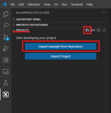
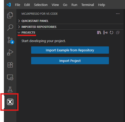
- 左側のアクティビティ・バーにあるMCUXpressoアイコンを見つけ、クリックして開きます。開いたら、エクスプローラに移動し、[PROJECTS(プロジェクト)]タブを開きます
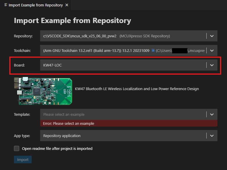
- [Import Example from Repository(リポジトリからサンプルをインポート)]をクリックします
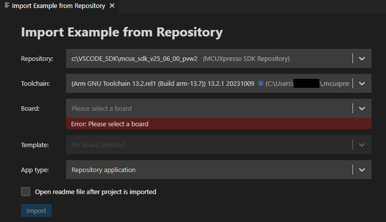
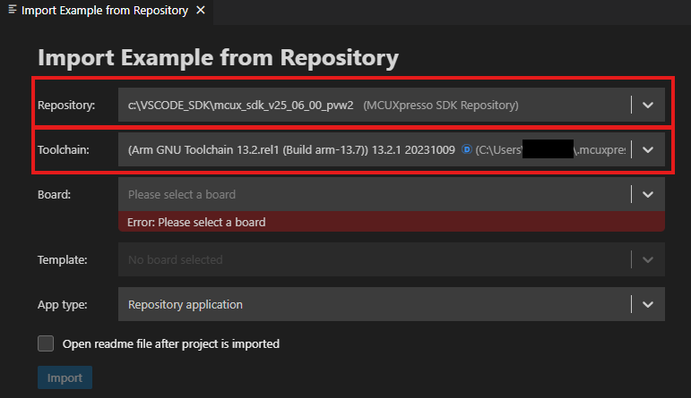
 編集画面に次のタブが表示されます
 - [Repository(リポジトリ)]タブの矢印ボタンをクリックして、前のステップでダウンロードしたSDKと、そのバージョンに対応するツールチェーンを選択します
- [Boards(ボード)]のドロップダウン・メニューからKW47-LOCボードを選択します
- 矢印ボタンを使用して[Template(テンプレート)]タブを展開し、プロジェクトで使用するテンプレートとして「
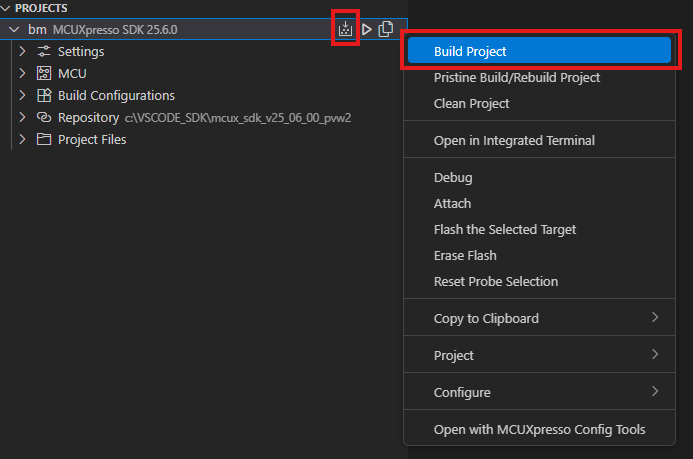
wireless_examples/bluetooth/bm/wireless_uart_bm」を選択します。その後、[Import(インポート)]ボタンをクリックします - プロジェクトを選択し、表示されているショートカットにある[Build(ビルド)]アイコンをクリックするか、[Build(ビルド)]オプションを右クリックして選択することで、プロジェクトをビルドします
- プロジェクトは、コンソールにエラーや警告が表示されることなくビルドされる必要があります
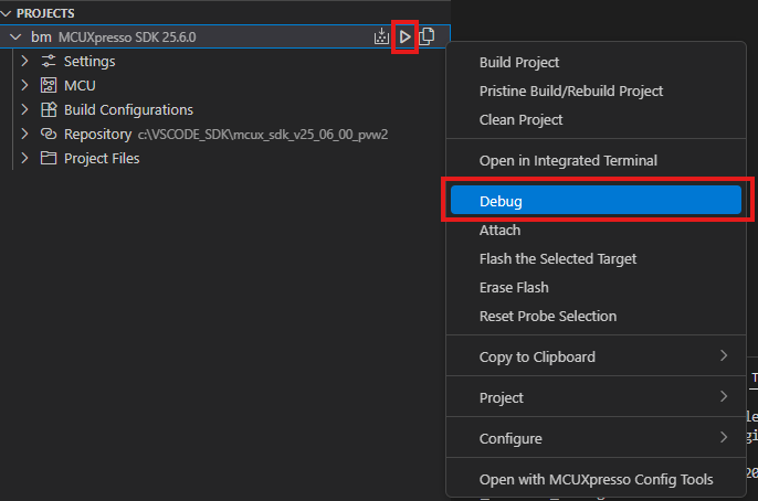
- micro-USBを
J3コネクタの「MCU-LINK」ポートに挿入し、ボードをコンピュータに接続します - [Debug(デバッグ)]アイコンをクリックするか、[Debug(デバッグ)]オプションを右クリックして選択することで、アプリケーションをボードにダウンロードします
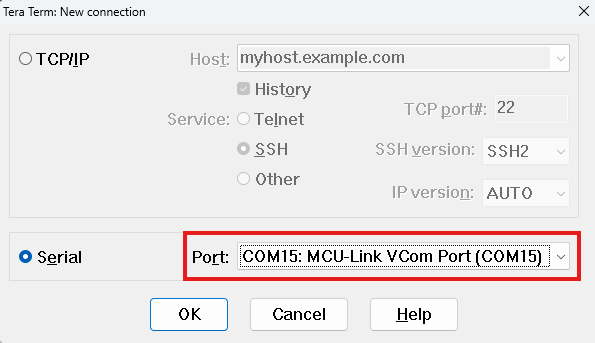
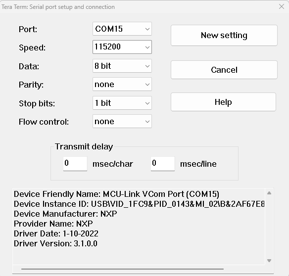
- シリアル・ターミナルを開いてアプリケーションの出力を確認し、ボードの「
MCULink-VCOM」ウィンドウで、MCULINKプローブに関連付けられたポートを選択します(ターミナルをボーレートまたは速度「115200」、8データ・ビット、パリティなし、1ストップ・ビットに設定した後、そのポートに接続します) - [Run(実行)]アイコンをクリックしてアプリケーションを実行します(ターミナルに表示される出力を確認します)
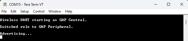
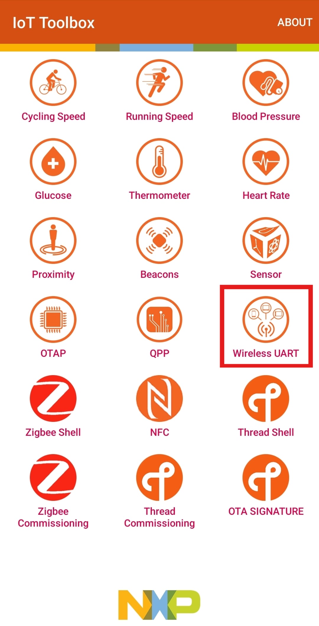
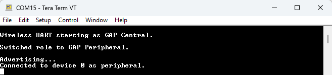
SW3ボタンを押して、Bluetooth® Low Energy (BLE) の役割をペリフェラルに切り替えます。次に、SW2を押して、BLEアドバタイジングを開始します(ターミナルに出力されるメッセージを確認してください)- IoT Toolboxアプリを使用し、メイン・メニューの[Wireless UART(ワイヤレスUART)]を選択してボードに接続します
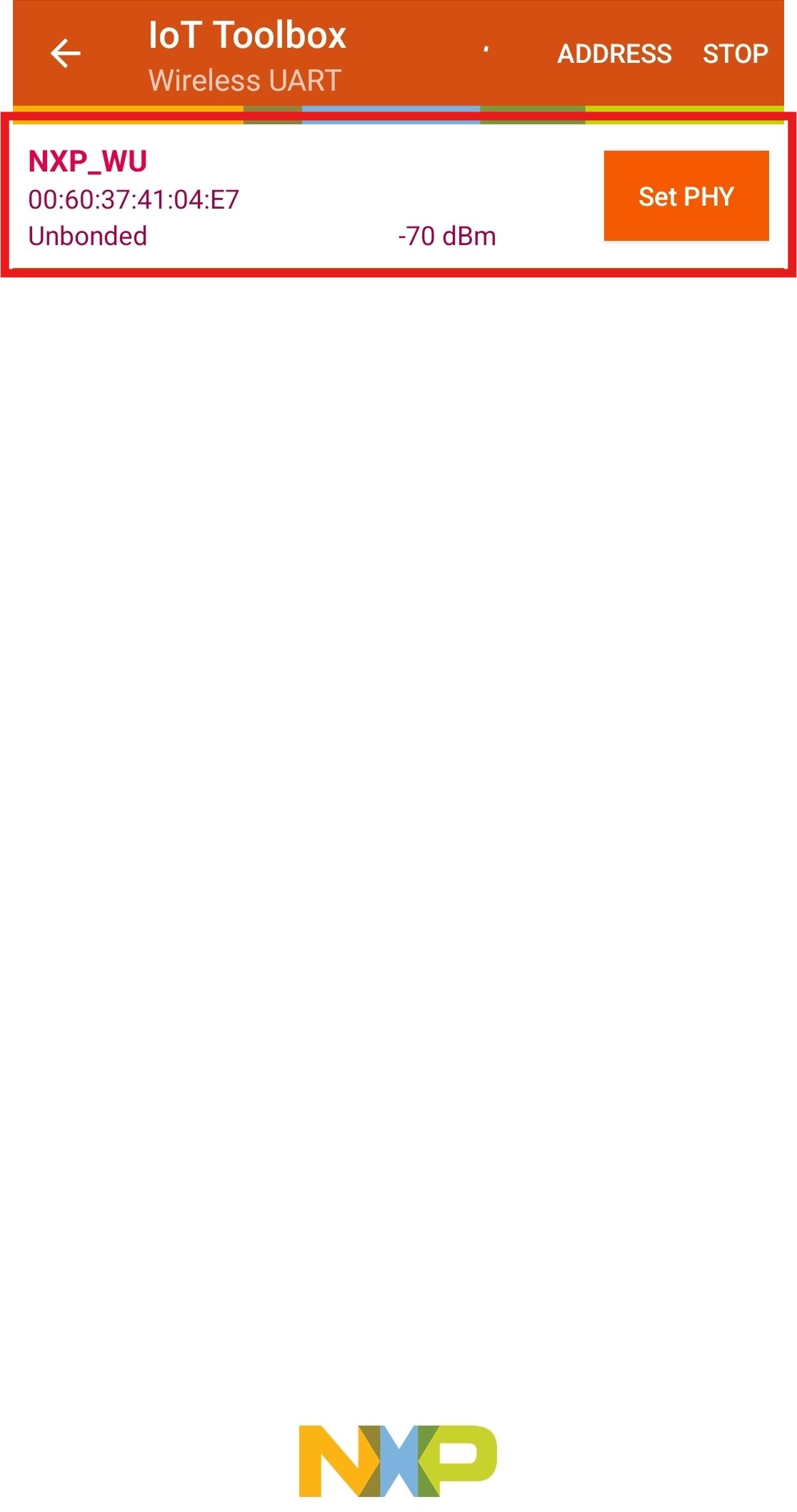
- 接続するボードを選択します(接続に関するメッセージがターミナルに表示されます)
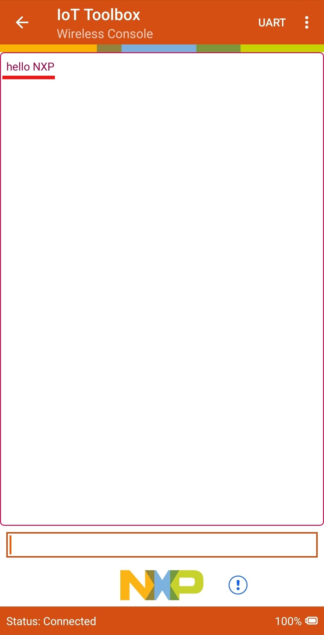
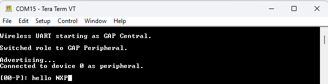
- アプリで任意のメッセージを入力し、シリアル・ターミナルにそのメッセージが表示されることを確認します
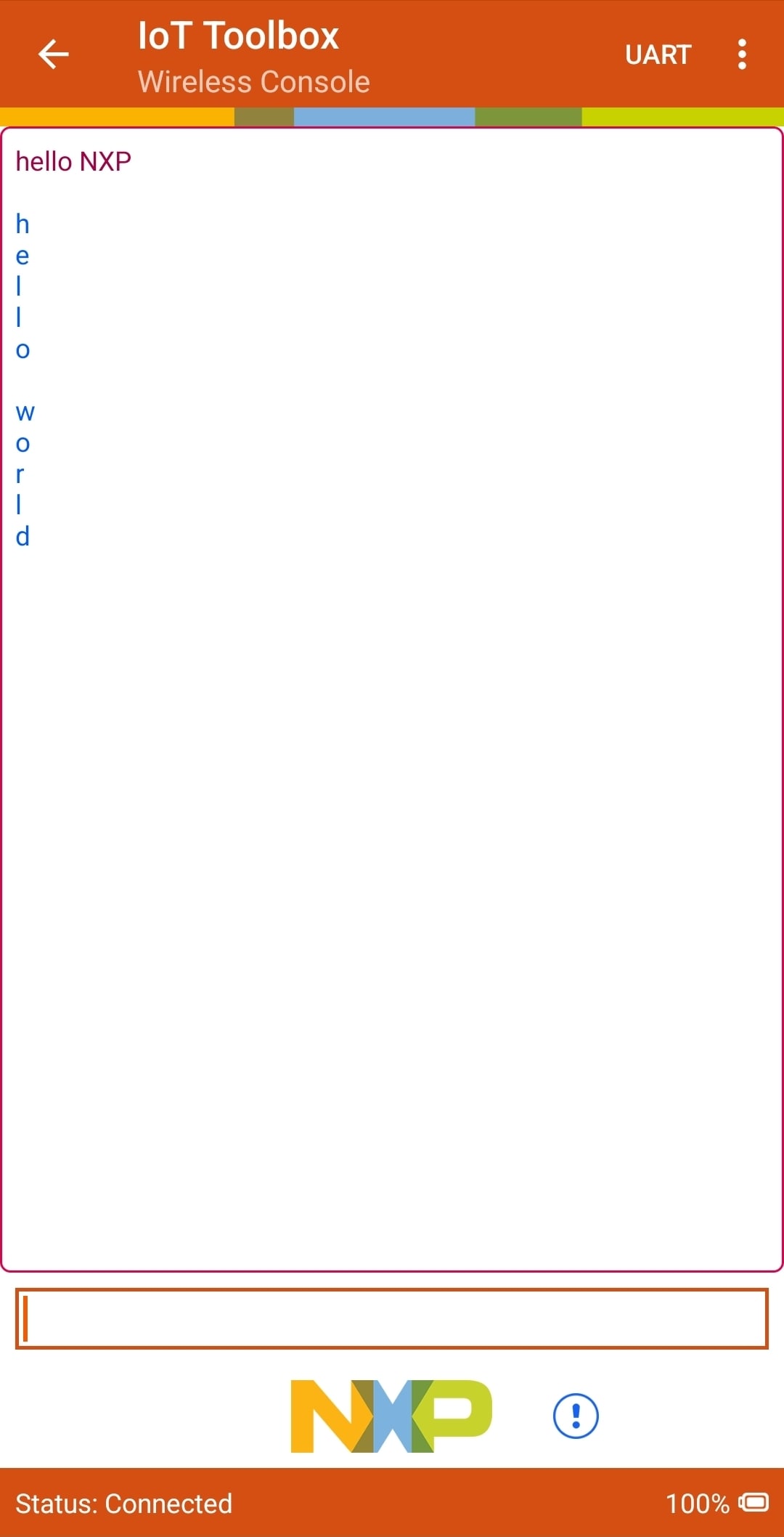
- ターミナルにメッセージを入力し、そのメッセージがアプリに表示されることを確認します


4. 作成
4.1 MCUXpresso for VS Codeからサンプル・プロジェクトのクローンを作成する
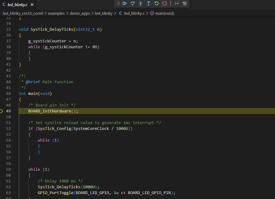
次の手順では、汎用出力 (GPO) の操作方法について説明します。この例では、LEDが毎秒切り替えるように設定されています。
- 前のセクションでの手順に従って、
led_blinkySDKサンプルをインポートします - [Import Example from Repository(リポジトリからサンプルをインポート)]ウィンドウの[Name(名前)]フィールド内の「
led_blinky_cm33_core0」プロジェクトをクリックし、前のセクションに記載されているようにデモをビルド、コンパイル、および実行します - これにより、青色LEDが毎秒切り替わるはずです
- これでデバッグ・セッションを終了します

4.2 MCUXpresso Config Toolsを使用する
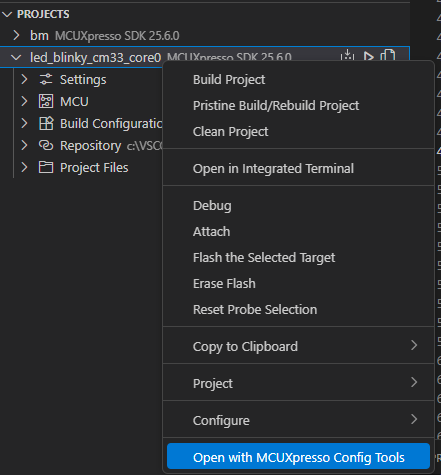
- プロジェクトを右クリックし、[Open with MCUXpresso Config Tools(MCUXpresso Config Toolsで開く)]を選択することで、ピン・ツールを開きます
- [Open existing configuration(既存の構成を開く)]オプションを選択し、SDKをインストールしたパス
mcuxsdk\examples\_boards\kw47loc\demo_apps\led_blinky\に移動したら、led_blinky.mexファイルを選択し、[Finish(完了)]をクリックします - これで、ピン・ツールにLED点滅プロジェクトのピン構成が表示されます
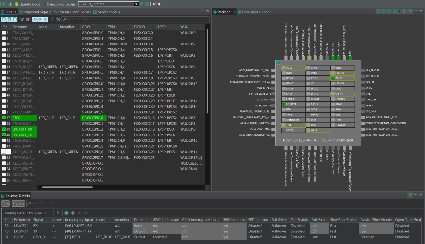
4.3 ピン・ツールを使用して、LEDがルーティングされたピンを変更する
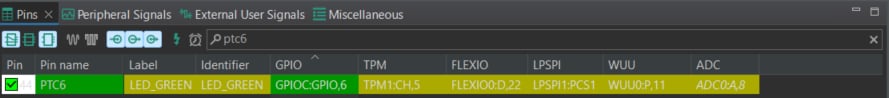
- [Pins(ピン)]ビューの[Show dedicated pins(専用ピンを表示)]および[Show not routed pins(ルーティングされていないピンを表示)]のチェックボックスのチェックを外し、ルーティングされているピンのみを表示させます(ピンの名称の横に緑色のボックスが表示されます。また、ルーティングされた各ピンに対して選択されている機能が緑色にハイライト表示されます)
- 現在の設定では、
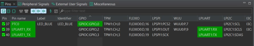
PTC0(LEB_BLUE) が出力としてルーティングされています。そこで、緑色LEDを有効にするためにピン構成を追加します - [Show not routed pins(ルーティングされていないピンを表示)]を選択して他のすべてのオプションを表示させ、
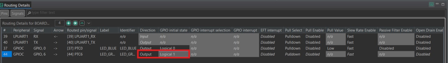
PTC6を検索して緑色LEDを有効にします。次に、汎用入出力 (GPIO) 列でGPIO6を選択します(同時ルーティングに関するメッセージが表示された場合は、「いいえ」を選択します) - 次に、[Routing Details(ルーティング詳細)]ウィンドウで
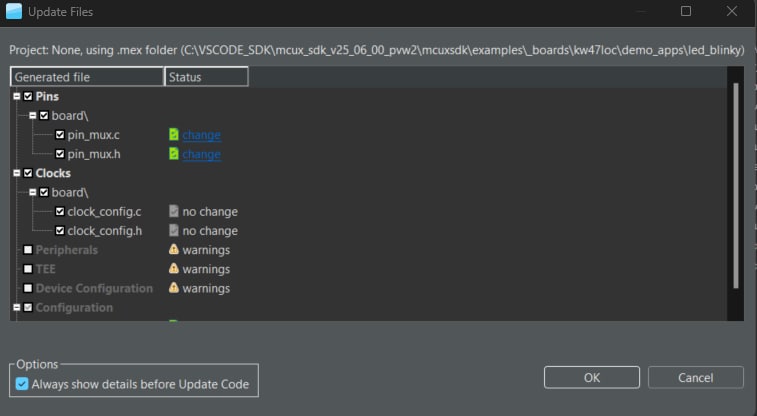
GPIOピンを出力として、またLogical 1をGPIOの初期状態として構成します - ここで、ピン・ツールによって生成された、新たに更新された
pin_mux.cファイルとpin_mux.hファイルをエクスポートして、これらの変更をプロジェクト内に実装します。そのため、メニュー・バーの[Update Code(コードの更新)]をクリックします - ポップアップ画面に変更するファイルが表示されるので、[OK]をクリックして新しいファイルをプロジェクトに上書きします。
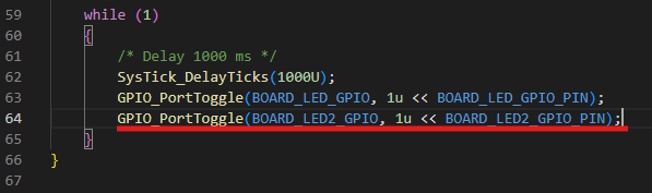
- 次に、サンプルに緑色LEDを切り替えるためのコードを追加します。
led_blinky.cファイルを開き、以下の行を追加します - 前のセクションでの手順に従って、プロジェクトをビルドしてダウンロードします
- アプリケーションを実行します(緑色と青色のLEDが交互に点灯するはずです)
- デバッグ・セッションを終了します

5. MCUXpresso開発者エクスペリエンス
以下の各セクションで、柔軟なプロトタイピングと開発のために提供されているエコシステムについてご覧ください。以下のビデオでは、FRDMプラットフォーム、フル機能のEVK、および拡張機能向けの互換シールドについて紹介しています。さらに、NXPのGitHubを通じて多数のアプリケーション・サンプルが提供されているアプリケーション・コード・ハブ (ACH) ポータルについて詳しく説明します。
5.1 FRDMプラットフォーム、フル機能のEVK、シールド
迅速なプロトタイピングのためのプラットフォームとして、低コストのFRDMプラットフォームまたはフル機能のEVKを選択できます。
FRDM開発ボードは、標準のフォーム・ファクタとヘッダー、MCU I/Oへの簡単なアクセス、オンボードMCU-Linkデバッガ、USB-Cケーブルを備えています。フル機能の評価キットには、I/Oおよびインターフェースへの拡張アクセス、Wi-Fi拡張機能のほか、追加のMCU-Link機能が含まれます。互換性のあるClickボードやArduinoシールドも多数あります。Open CMSIS Packでサポートされているデバイスについては、ACHでサンプルが提供されている場合があります。そうでない場合でも、その多くがI²C (Inter-Integrated Circuit)、シリアル・ペリフェラル・インターフェース (SPI)、汎用非同期送受信回路 (UART) などのシリアル・インターフェースを利用して容易に使用でき、MCUXpresso SDKでドライバとサンプルが提供されています。
5.2 アプリケーション・コード・ハブ
ACHは、ソフトウェアをすばやく見つけることができるインタラクティブなダッシュボードであり、NXPのMCUXpresso開発者エクスペリエンスをさらに向上させます。ACHに今すぐアクセスして、この新しいインタラクティブなアプリケーション・コード・ハブの詳細やその利点について確認しておきましょう。
ACHのソフトウェアはNXPのGitHubリポジトリに置かれているため、その場所に直接アクセスして簡単にクローンを作成することができます。
5.3 デモのご紹介
次のデモでは、モータ制御シールドと低コストLCDを備えた、FRDMプラットフォームを基盤とするシステムを使用して、ACHからプロジェクトをインポートする方法を示しています。評価ボードがこのシステムと異なる場合でも、以降の手順はサポート対象のすべてのプラットフォームで同じように実施できます。