S32K3X4EVBボードのクイック・スタート・ガイド
サインイン 進行状況を保存するには アカウントをお持ちでない方 アカウントを作成する。
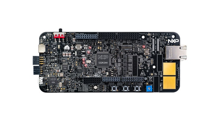
お客様の S32K3x4-Q172 General-Purpose Development Board
1. パッケージの内容
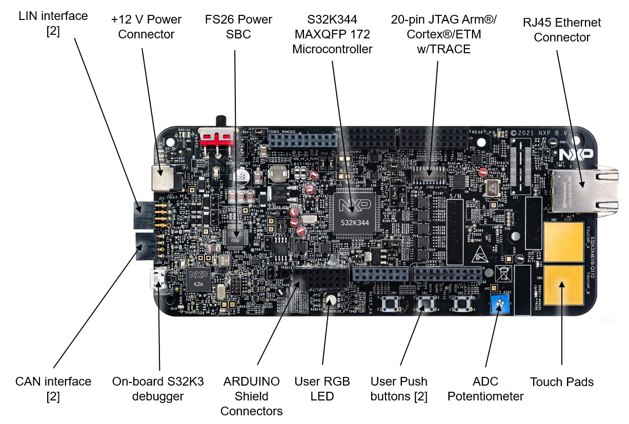
1.1 S32K344EVB-Q172評価ボードについて
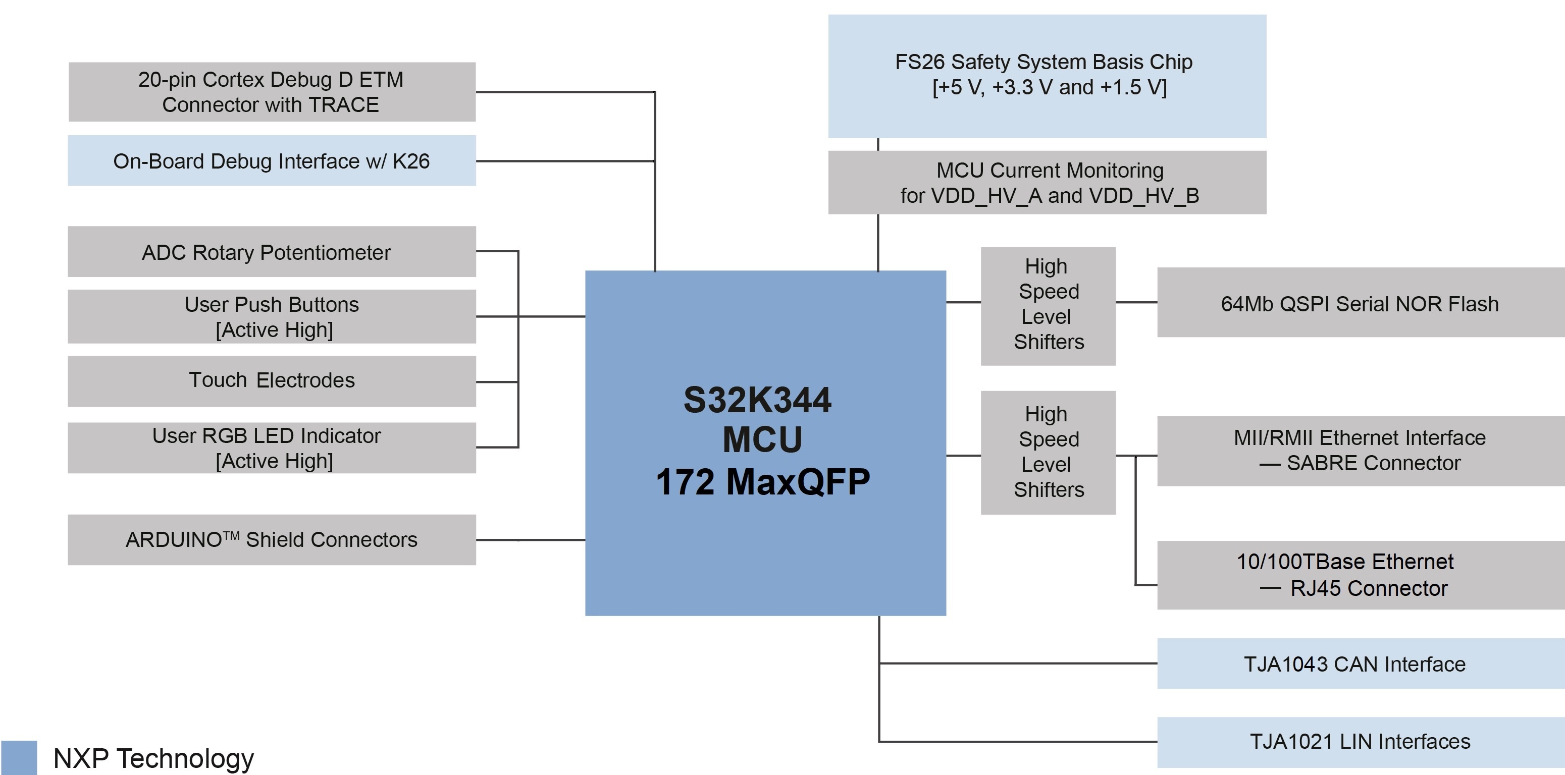
1.2 ブロック図の特長
2. ソフトウェアの入手
ビデオをご覧いただくか、以下のステップ・バイ・ステップ・ガイドに従ってS32K3X4EVB-Q172評価ボードをセットアップしてください。
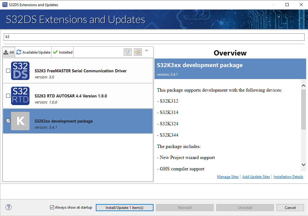
2.2 S32K3xx開発パッケージのインストール
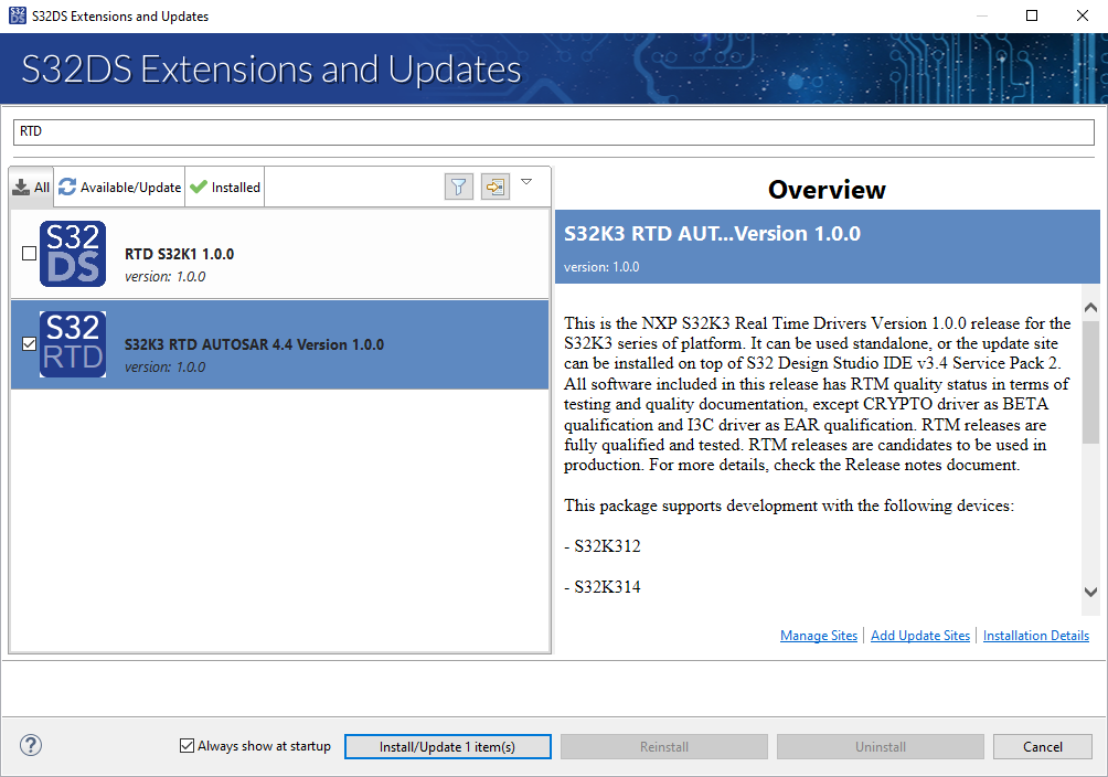
トップメニューから[Help(ヘルプ)]>[S32DS Extensions and Updates(S32DSの拡張と更新)]の順に進み、[S32DS Extensions and Updates(S32DSの拡張と更新)]を開きます。「S32K3xx development package(S32K3xx開発パッケージ)」に移動して、パッケージをインストールします。
S32K3xx用リアルタイム・ドライバのインストールを続行します。
2.3 Elektrobit tresos Studioおよびリアルタイム・ドライバのダウンロードとインストール(AUTOSAR®ユーザーのみ)
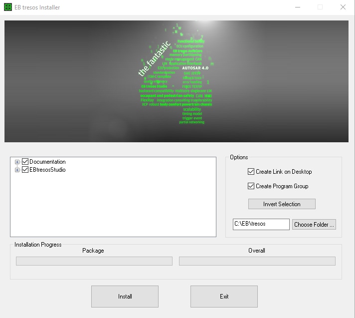
S32K3標準ソフトウェア・パッケージからElektrobit tresos Studio / AUTOSAR設定ツールをダウンロードし、インストールしてください。
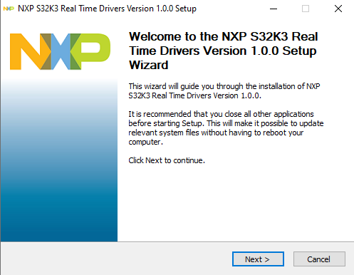
S32K3標準ソフトウェア・パッケージからCortex-M向けS32K3リアルタイム・ドライバの.exeファイルをダウンロードし、インストールしてください。
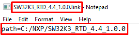
インストーラは、設定の時間を節約するために、ディスク上のEB tresosのインストール・ディレクトリを要求します。
2.4 ランタイム・デバッグ・ツールの入手
S32K3X4EVB-Q172は、FreeMASTERランタイム・デバッグ・ツールを使用するとパフォーマンスが向上します。
S32K3マイクロコントローラ用のFreeMASTER通信ドライバも必要です。S32K3標準ソフトウェア・パッケージの車載ソフトウェア - S32K3 - S32 FreeMASTERのリンクからダウンロードしてください。
3. 接続
3.1 S32K3X4EVB-Q172評価ボードのジャンパの設定
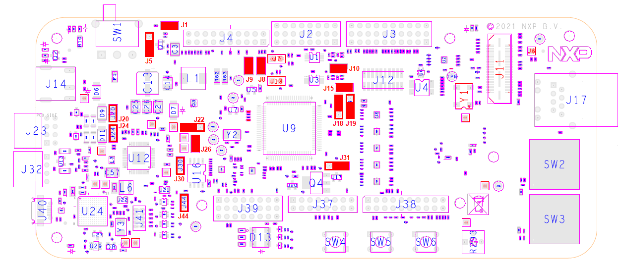
| デフォルトのジャンパ設定 | ||
|---|---|---|
| ジャンパ | 状態 | 備考 |
J1 |
閉 | 電源投入後にFS26のウォッチドッグを無効化 |
J5 |
1-2 | FS26のデバッグ・ピンの電圧レベルを選択 |
J8 |
閉 | VDD_HV_Bドメインから外部回路に給電 |
J9 |
閉 | VDD_HV_Aドメインから外部回路に給電 |
J10 |
閉 | VDD_HV_AドメインからMCUペリフェラルに給電 |
J15 |
閉 | VDD_HV_BドメインからMCUペリフェラルに給電 |
J18 |
1-2 | VDD_HV_Aドメイン用5 V |
J19 |
1-2 | VDD_HV_Bドメイン用3.3 V |
J20 |
開 | LIN1コントローラ・モード |
J22 |
1-2 | FS26 SBCからの5 V |
J24 |
開 | LIN2コントローラ・モード |
J26 |
閉 | FS26 SBCからの3.3 V |
J30 |
開 | FS26ウェイク入力 |
J31 |
1-2 | FS26 SBCからV15ドメインに給電 |
J44 |
開 | オンボード・デバッガUARTピン |
3.2 電源の接続
SW1をOFFポジション(右端)に切り替えます。
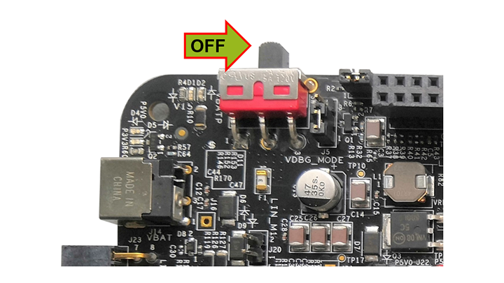
12 V電源アダプタを接続し、SW10をONポジション(左端)に切り替えます。
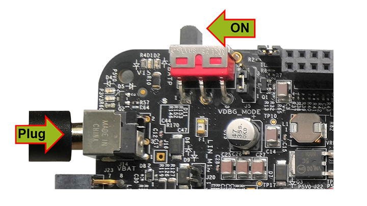
この電源投入手順では、SBCはウォッチドッグが無効の状態で起動します。4つのオレンジ色のLEDは、アクティブな12 V、5 V、3.3 V、および1.5 V電源ドメインを示します。
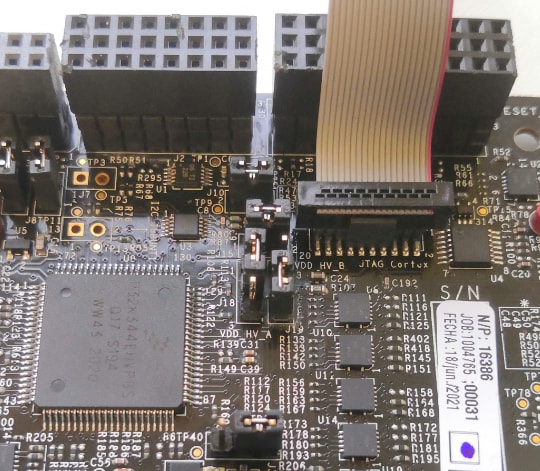
3.3 デバッガ・ケーブルの接続
オンボードのS32K3デバッガを使用してデバッグする場合は、J40コネクタにmicro-USBケーブルを接続します。
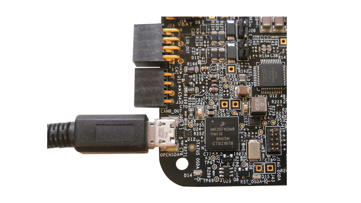
または、外部のS32K3デバッガを使用してデバッグする場合は、利用可能なJTAGコネクタの1つを使用します。
4. ビルドと実行
S32K3X4EVB-Q172評価ボードを実際に使ってみましょう。
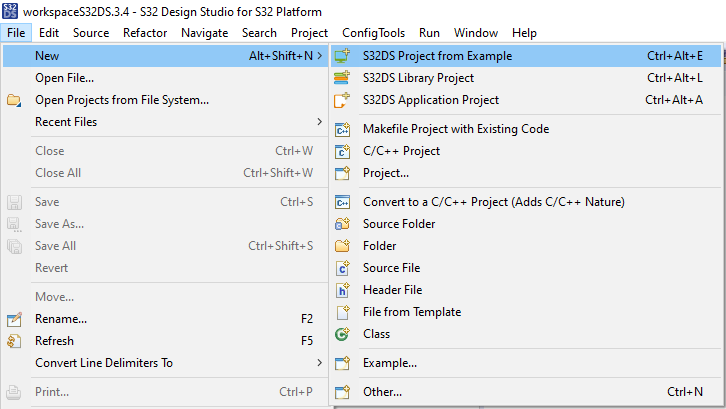
4.1 サンプルに基づいた新規S32DSプロジェクトの作成
S32DSを開き、メニューから[File(ファイル)]>[New(新規)]>[S32DS Project from Example(サンプルに基づいたS32DSプロジェクト)]の順に選択します。RTDのサンプル・コードの1つを選択します。高レベルAPIのサンプルまたは低レベルAPIのサンプルを選択できます。例:Port_example_K344。
4.2 設定ツールの使用
.mexプロジェクト・ファイルをダブルクリックします。
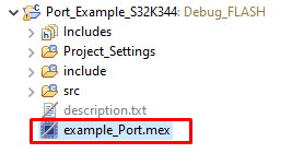
適切なプロジェクトを設定していることを確認し、[Update Code(コードの更新)]ボタンをクリックして設定ファイルを生成します。

4.3 ソフトウェアのアップロードとデバッグ
C/C++画面に戻ります。

[Debug Configuration(デバッグ設定)]メニューを使用し、ソフトウェアをビルドしてMCUにアップロードするための定義済みデバッグ設定の1つを選択します。

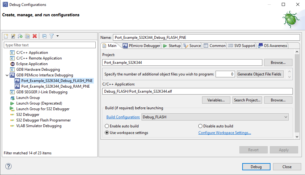
S32DSがデバッグ画面に切り替わります。この画面でコードを実行できます。

赤色LEDが約10秒間点滅します。
設計・リソース
ボード情報
チップに関するドキュメント
サポート
トレーニング
フォーラム
NXPのコミュニティ・サイトで、他のエンジニアとつながり、S32K3X4EVB-Q172評価ボードを使用した設計に関する専門的なアドバイスを受けることができます。