RDI7018C3T1のスタート・ガイド
このドキュメントの内容
-
パッケージの内容
-
ハードウェアの入手
-
ハードウェアの構成
サインイン 進行状況を保存するには アカウントをお持ちでない方 アカウントを作成する。
お客様の RDI7018C3T1
1. パッケージの内容
NXPのアナログ製品開発ボードは、NXP製品の評価を目的とした使いやすいプラットフォームです。さまざまなアナログ・ソリューション、ミックスド・シグナル・ソリューション、パワー・ソリューションに対応しています。実績のある大容量テクノロジを使用したモノリシック集積回路およびシステム・イン・パッケージ (SiP) デバイスを搭載しています。NXP製品は、最先端システムへの電源供給において、より長いバッテリー寿命、より小さいフォーム・ファクタ、より少ない部品数、より低いコスト、より優れたパフォーマンスを実現します。
このページでは、RDI7018C3T1ボードをセットアップして使用する手順について説明します。
1.1 キットの内容と同梱物一覧
キットには以下のものが含まれています。
- 組立ておよびテスト済み評価ボード/モジュール(静電気防止バッグ入り)
- セル端子ケーブル x 3
- トランスポート・プロトコル・リンク (TPL) 通信用ケーブル x 1
- クイック・スタート・ガイド
1.2 追加ハードウェア
このキットを使用するには、次のハードウェアが必要です。
- 4セル~18セルのバッテリー・パック、またはBATT-18EMULATORなどのバッテリー・パック・エミュレータ
- TPL通信システム
- 評価用セットアップは、FRDM665SPIEVB(MC33665A用EVB)とS32K3X4EVB-T172 (S32K3 MCU) の組み合わせで構成されています
- 評価用セットアップでは、EvalGUI 7を使用できます
2. ハードウェアの入手
2.1 キットの概要
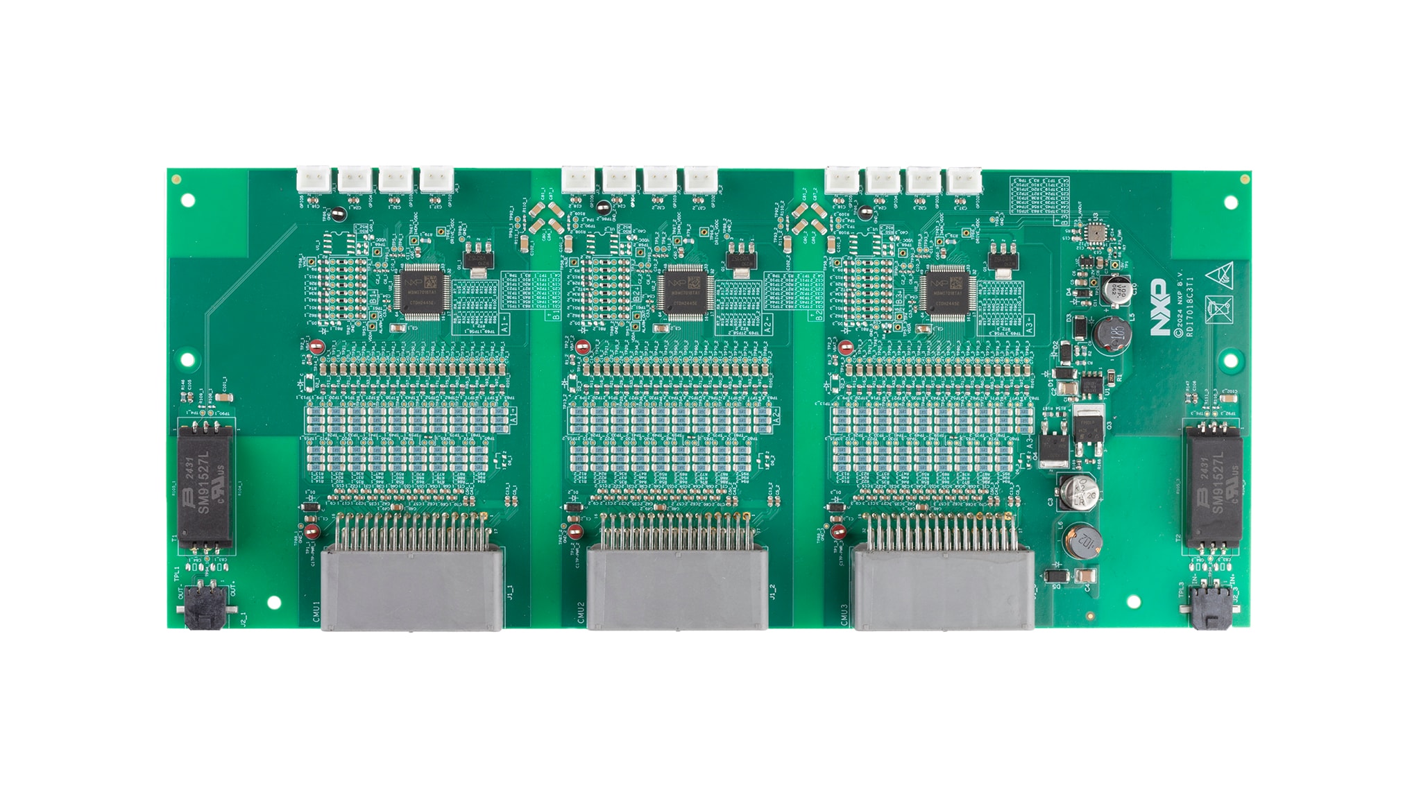
RDI7018C3T1は、NXP BMI7018デバイスをサポートするハードウェア評価ツールです。RDI7018C3T1は、3つのBMI7018バッテリー・セル・コントローラICを実装しています。BMI7018は、最大18個のリチウムイオン・バッテリー・セルを監視するバッテリー・セル・コントローラです。インダストリアル用途での使用を想定して設計されています。このデバイスは、セルの差動電圧に対してアナログ・デジタル変換を実行します。温度測定にも対応し、I²Cバスを介して他のデバイスに情報を転送できます。RDI7018C3T1は、電圧および温度の検知に関わるBMI7018ベース・アプリケーションの迅速なプロトタイプ作成に最適なプラットフォームです。
RDI7018C3T1は、オンボードのFXPS7250A4ST1圧力センサを使用してバッテリー・モジュールの圧力を測定します。RDI7018C3T1は、TEA1721AT/N1、118フライバック・コントローラを使用してバッテリー・モジュール電圧を12 Vに変換した後、12 Vを5 Vに変換して圧力センサに電力を供給します。
RDI7018C3T1は、オフボード通信に誘導性絶縁を使用しています。オンボード通信用のガルバニック絶縁はキャパシタによって確立されます。

3. ハードウェアの構成
3.1 バッテリー・エミュレータの接続
1つのBMI7018で最小4セル、最大18セルを監視できます。NXPは、18セル・バッテリーのエミュレータ・ボードであるBATT-18EMULATORを提供しています。このボードを使用することで、エミュレートされたバッテリー・パックの18セルの電圧をセル単位で直感的に変更することができます。RDI7018C3T1ボードは、コネクタJ1_1、J1_2、J1_3と付属の電源ケーブルを使用して、18セルのバッテリー・エミュレータ・ボードに接続できます。図2を参照してください。

