QN9080SIP-DKのスタート・ガイド
このドキュメントの内容
-
接続
-
ソフトウェアの入手
-
ビルドと実行
サインイン 進行状況を保存するには アカウントをお持ちでない方 アカウントを作成する。
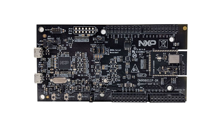
お客様の QN9080SIP Development Kit
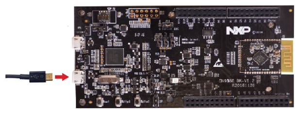
1. 接続
QN9080SIP-DKボードを実際に使ってみましょう。ショート・ビデオで手順を視聴するか、以下に記載された詳細な手順を参考にして、作業を進めてください。
1.1 QN9080SIP-DK開発キットのスタート・ガイド
2. ソフトウェアの入手
2.1 QN9080SIP-DK用ソフトウェアのインストール
2.2 MCUXpresso SDKとコネクティビティ・ソフトウェアのダウンロード
QN9080SIP-DK向けのMCUXpresso SDKに統合されているMCUXpressoソフトウェア開発キットには、Bluetooth Low Energyを利用したソリューションを開発するために必要なワイヤレス接続スタックがすべて含まれます。
QN9080SIP-DK向け事前構成済みSDKリリースをダウンロードするには、以下をクリックしてください。これにはQN9080用のワイヤレス・コネクティビティBluetooth Low Energyスタックが含まれます。

2.3 ツールチェーンをインストールする
NXPは、MCUXpresso IDEというツールチェーンを無償で提供しています。

別のツールチェーンを使用したい場合は?
問題ありません。MCUXpresso SDKは、IARやKeilなどの他のツールをサポートしています。

2.4 MCUXpresso Config Tools
MCUXpresso Config Toolsは、ユーザーがMCUXpresso SDKプロジェクトを新規に作成するための構成ツールの統合スイートであり、カスタム・ボード・サポート用の初期化Cコードを生成するためのピン・ツールとクロック・ツールも備えています。このツールはMCUXpresso IDEに統合されていますが、別のIDEを使用している場合は、以下からこのツールをダウンロードできます。

2.5 QN9080SIP-DKドライバ
デバッガおよび仮想COMポート用のドライバもインストールする必要があります。これらはLPCScryptパッケージの一部であり、以下からダウンロードできます。LPScryptをインストールしたら、QN9080SIP-DKボードがコンピュータに接続されていることを確認した後、C:\NXP\LPCScrypt\Driversフォルダにあるlpc_driver_installer.exeをダブルクリックしてドライバをインストールします。
2.6 ターミナルの設定
任意のターミナルをボーレート115,200、8データ・ビット、パリティなし、1ストップ・ビットに設定します。QN9080SIP-DKの仮想COMポートのポート番号は、デバイス・マネージャを開き、「Ports(ポート)」グループで確認します。
ターミナル・アプリケーションの使用方法がわからない場合は、Tera TermチュートリアルまたはPuTTYチュートリアルのいずれかのチュートリアルをお試しください。
3. ビルドと実行
QN9080ワイヤレス・コネクティビティ・スタックには、すぐにコンパイルして実行できるデモ・アプリケーションやドライバのサンプルが付属しています。
3.1 Q9080SIP-DKでデモをビルドして実行する
3.2 コネクティビティ・サンプル・コードを確認する
QN9080ワイヤレス・コネクティビティ・ソフトウェア・パッケージには、BLEのサンプルが多数収録されています。利用可能なサンプルを確認するには、「wireless_examples」フォルダ (
ボードに付属するプログラム済みのサンプルを実行する場合は、こちらをクリックしてください。
3.3 スマートフォン用のBLE Toolboxをダウンロードする
Bluetooth Low Energyのサンプルを使用するには、スマートフォンにNXP IoT Toolboxがインストールされている必要があります。このアプリケーションには、コネクティビティ・スタックと組み合わせて使用し、BLE経由でスマートフォンを開発ボードに接続できる、いくつかのサンプルが用意されています。
3.4 ワイヤレス・コネクティビティ・サンプルのビルド、実行、デバッグ
ご自身でデモをビルドし、デバッグすることも可能です。以下のガイドを使用して、MCUXpresso IDEやIAR Embedded Workbench IDEでワイヤレス・コネクティビティ・スタックのサンプル・アプリケーションのビルドやデバッグを行う方法を習得してください。
MCUXpresso IDEを使用してデモを実行する
MCUXpresso SDKのインポート
- MCUXpresso IDEを開きます
- MCUXpresso IDEウィンドウ内のビューを[Installed SDKs(インストール済みSDK)]に切り替えます
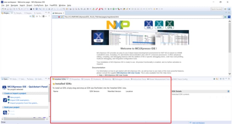
- Windowsエクスプローラを開き、QN9080SIP-DK SDKディレクトリを[Installed SDKs(インストール済みSDK)]ビューにドラッグ&ドロップします
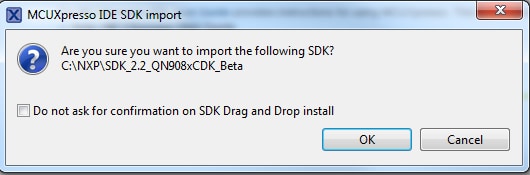
- 次のポップアップが表示されます。[OK]をクリックしてインポートを続けます:
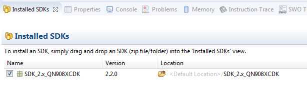
- インストールされたSDKは、以下に示すように[Installed SDKs(インストール済みSDK)]ビューに表示されます。
BLEアプリケーションのビルド
次の手順に従ってハイブリッド・サンプルを開きます。このプロジェクトは1番目のボードにロードされ、もう1つのプロジェクトは2番目のボードにロードされます。
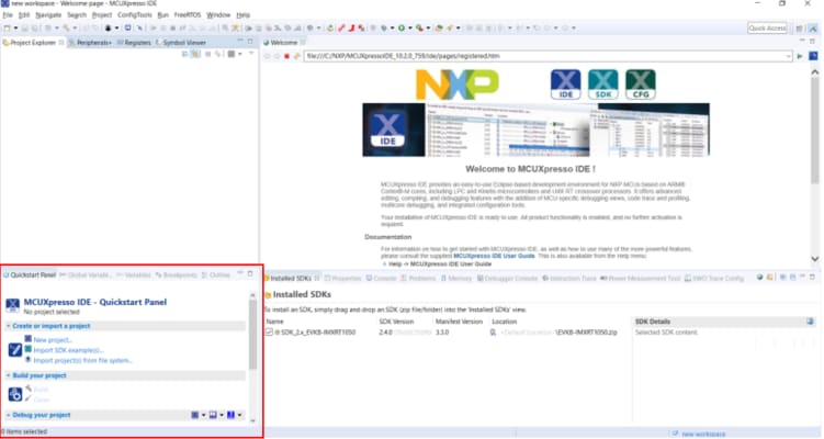
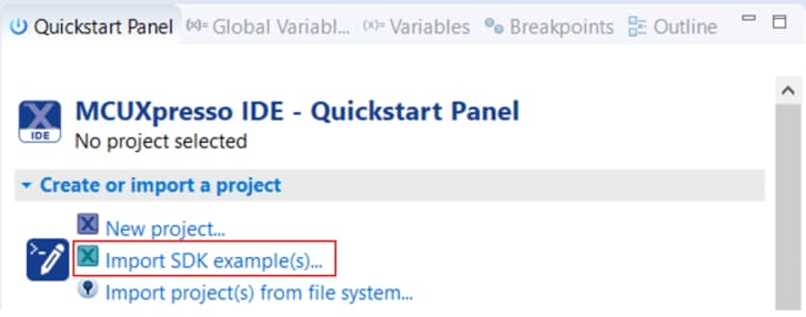
- 左下隅にある「Quickstart Panel(クイックスタート・パネル)」を確認します
- 次に、[SDKサンプルをインポート(Import SDK examples(s))]をクリックします
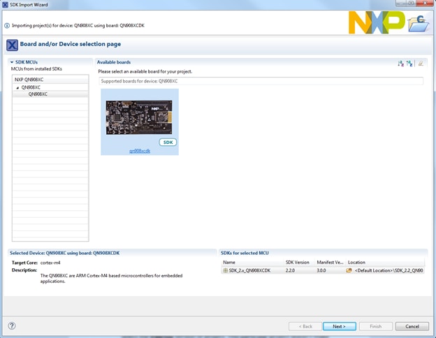
- サンプルをインポートして実行させるボードとしてQN9080SIP-DKボードをクリックして選択し、[Next(次へ)]をクリックします
-
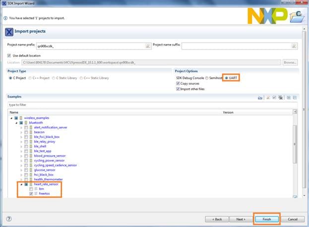
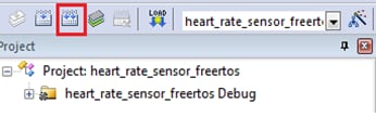
次に、インポートするプロジェクトを選択する必要があります。矢印ボタンを使用して「wireless_examples」カテゴリを展開したら、「bluetooth」カテゴリにある「heart_rate_sensor」プロジェクトを展開し、プロジェクトの「freertos」バージョンを選択します
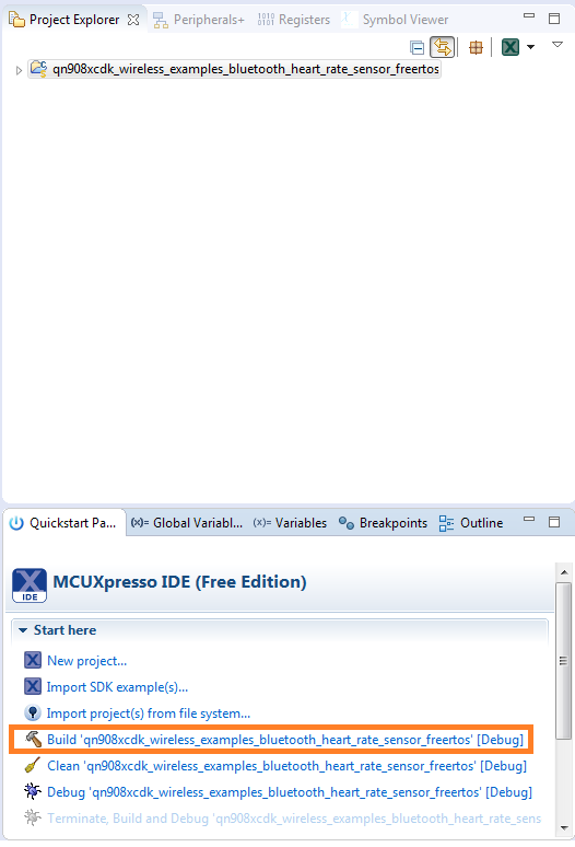
- 「qn908xcdk_wireless_examples_bluetooth_heart_rate_sensor_freertos」プロジェクトをクリックし、クイックスタート・パネルの[Build(ビルド)]をクリックして、プロジェクトをビルドします
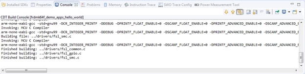
- ビルドの進捗状況は[Console(コンソール)]タブで確認できます。コンパイル・エラーが発生した場合は、2つのプロジェクトが同時にインポートされているかどうか確認してください
このプロジェクトではUARTを使用しませんが、使用するプロジェクトの場合は、[SDK Debug Console(SDKデバッグ・コンソール)]で[UART]オプションを選択してください。[Finish(完了)]をクリックします
アプリケーション・デモのダウンロードと実行
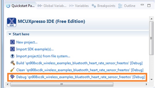
- 1番目のQN9080SIP-DKボードをまだPCに接続していなければ、接続します。QN9080SIP-DKの
J2USBコネクタを使用します - クイックスタート・パネルを開き、[Debug ‘qn908xcdk_wireless_examples_bluetooth_heart_rate_sensor_freertos’ [Debug](デバッグ 'qn908xcdk_wireless_examples_bluetooth_heart_rate_freertos' [デバッグ])]をクリックします
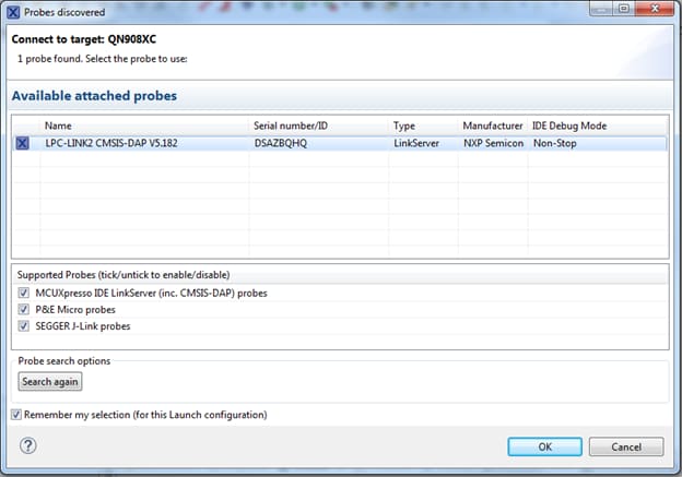
- MCUXpresso IDEが接続済みのボードを調査し、QN9080SIP-DKのデバッグ集積回路の一部であるLPC-LINK2 CMSIS-DAPデバッグ・プローブを検出します。[OK]をクリックして続行します
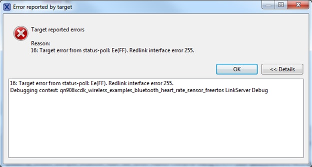
- 次のエラーが発生する可能性があります。[OK]をクリックして無視します
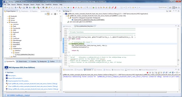
- ファームウェアがボードにダウンロードされ、デバッガが起動します
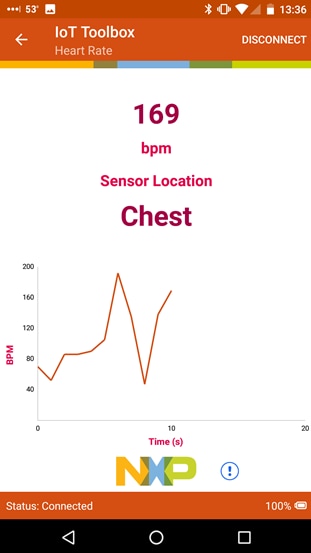
心拍数センサ・デモの実行
- モバイル機器でNXP IoT Toolboxアプリを開き、[Heart Rate(心拍)]アイコンをクリックします

- QN9080SIP-DKボードの
Button1を押して、BLEアドバタイジングを開始します - スマートフォン・アプリに「FSL_HRS」が表示されますそれをクリックします
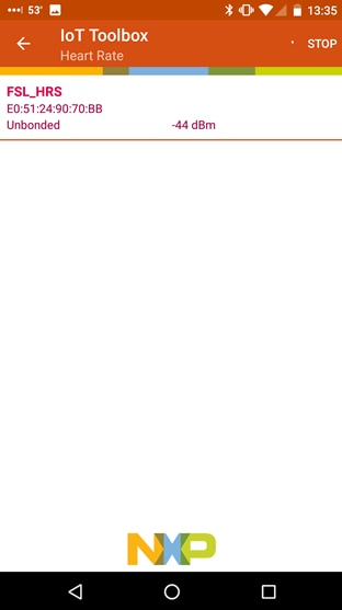
- ボードがスマートフォンに接続すると、ランダムなBPM読み取り値のグラフが表示されます

IARを使用してデモを実行する
以下の手順では、QN9080SIP-DKボードを使用した簡単な心拍数センサBLEアプリケーションをコンパイルしてフラッシュし、実行するまでの方法を説明します。
BLEアプリケーションのビルド
- Heart Rate Sensorワークスペースに移動します (
\boards\qn908xcdk\wireless_examples\bluetooth\heart_rate_sensor\freertos\iar 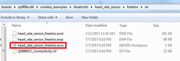
- ワークスペースが開いたら、プロジェクトを選択します
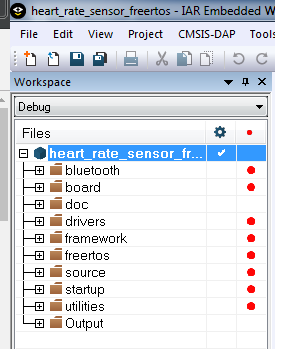
- [Make(作成)]ボタンをクリックしてプロジェクトをビルドします
アプリケーション・デモのダウンロードと実行
- 1番目のQN9080SIP-DKボードをまだPCに接続していなければ、接続します。QN9080SIP-DKの
J2USBコネクタを使用します - PCのターミナル・アプリケーション(PuTTY、Tera Termなど)を開き、事前に確認したデバッグCOMポートに接続します。ターミナルを次のように設定します

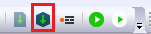
- [Download and Debug(ダウンロードとデバッグ)]ボタンをクリックして、アプリケーションをターゲットにダウンロードします

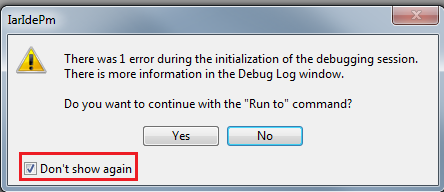
- ファームウェアがボードにダウンロードされます。その後、次のメッセージが表示される場合があります。[Don't show again(今後表示しない)]チェックボックスにチェックを入れ、[Yes」ボタンをクリックします
- その後で、デバッガが起動します。[Go(実行)]ボタンをクリックしてデモの実行を開始します
心拍数センサ・デモの実行
- モバイル機器でNXP IoT Toolboxアプリを開き、[Heart Rate(心拍)]アイコンをクリックします
- QN9080SIP-DKボードの
Button1を押して、BLEアドバタイジングを開始します - スマートフォン・アプリに「FSL_HRS」が表示されますそれをクリックします
- ボードがスマートフォンに接続すると、ランダムなBPM読み取り値のグラフが表示されます
Keil® MDK/µVision®を使用してデモを実行する
CMSISデバイス・パックのインストール
MDKツールをインストールした後、デバッグ目的でデバイスを完全にサポートするには、CMSIS (Cortex® Microcontroller Software Interface Standard) デバイス・パックをインストールする必要があります。このパックには、メモリ・マップ情報、レジスタ定義、フラッシュ・プログラミング・アルゴリズムなどが含まれています。下記の手順に従って、適切なCMSISパックをインストールしてください。
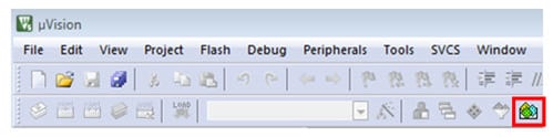
- µVisionという名前のMDK IDEを開きます。IDEで[Pack Installer(パック・インストーラ)]アイコンを選択します
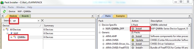
- [Pack Installer(パック・インストーラ)]ウィンドウで「qn」を検索し、QN908xファミリを表示させます。「QN908x」をクリックすると、右側に「NXP::QN908x_DFP」パックが表示されます。パックの横にある[Install(インストール)]ボタンをクリックします。このプロセスを正常に完了するには、インターネット接続が必要となります
- インストールが完了したら、[Pack Installer(パック・インストーラ)]ウィンドウを閉じて、µVision IDEに戻ります
サンプル・アプリケーションのビルド
次の手順に従って「heart_rate_sensor」BLEデモを開きます。
- MDK内で、[Project(プロジェクト)]→[Open Project(プロジェクトを開く)]をクリックします
- Heart Rate Sensorワークスペース (
\boards\qn908xcdk\wireless_examples\bluetooth\heart_rate_sensor\freertos\keil 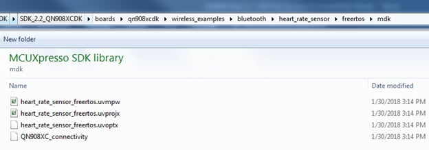
- デモ・プロジェクトをビルドするには、赤色でハイライト表示されている[Rebuild(リビルド)]ボタンを選択します
- ビルドが正常に完了します
サンプル・アプリケーションの実行
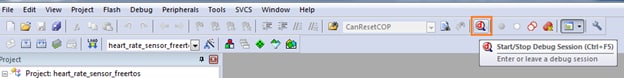
- 1番目のQN9080SIP-DKボードをまだPCに接続していなければ、接続します。QN9080SIP-DKの
J2USBコネクタを使用します - [Start/Stop Debug Session(デバッグ・セッションの開始/停止)]ボタンをクリックして、コードをボードにダウンロードし、デバッグを開始します
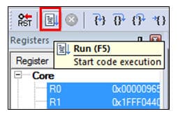
- [Run(実行)]ボタンをクリックすると、コードが実行され、アプリケーションが起動します
心拍数センサ・デモの実行
- モバイル機器でNXP IoT Toolboxアプリを開き、[Heart Rate(心拍)]アイコンをクリックします
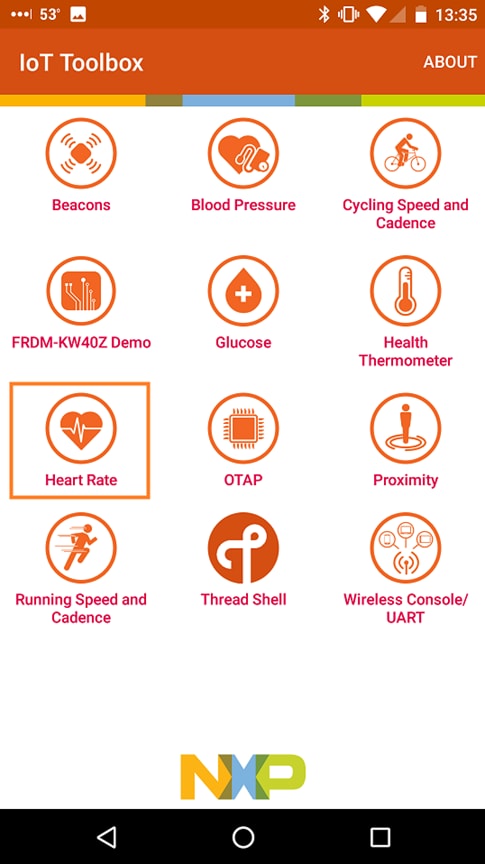
- QN9080SIP-DKボードの
Button1を押して、BLEアドバタイジングを開始します - スマートフォン・アプリに「FSL_HRS」が表示されますそれをクリックします

- ボードがスマートフォンに接続すると、ランダムなBPM読み取り値のグラフが表示されます
Tera Termチュートリアル
Tera Termチュートリアル
Tera Termは、広く利用されているオープンソースのターミナル・エミュレーション・アプリケーションです。このプログラムを使用して、NXP開発プラットフォームの仮想シリアル・ポートから送信された情報を表示できます。
- SourceForgeからTera Termをダウンロードします。ダウンロードしたら、インストーラを実行し、このウェブページに戻って手順を続行します
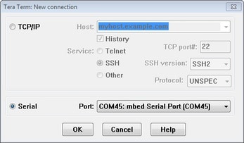
- Tera Termを起動します。初めて起動する際には、次のダイアログが表示されます。[Serial(シリアル)]オプションを選択します。ボードが接続されている場合は、COMポートが自動的にリスト内に表示されます
- 事前に確認したCOMポート番号を使用して、シリアル・ポートをボーレート115,200、8データ・ビット、パリティなし、1ストップ・ビットに設定します。この設定は[Setup(セットアップ)]>[Serial Port(シリアル・ポート)]から行うことができます
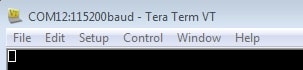
- 接続が確立されているか検証します。確立されている場合、Tera Termのタイトル・バーに次のように表示されます
- 以上で設定は完了です
PuTTYチュートリアル
PuTTYチュートリアル
PuTTYは、広く利用されているターミナル・エミュレーション・アプリケーションです。このプログラムを使用して、NXP開発プラットフォームの仮想シリアル・ポートから送信された情報を表示できます。
- 下のボタンをクリックしてPuTTYをダウンロードします。ダウンロードしたら、インストーラを実行し、このウェブページに戻って手順を続行します
- 選択したダウンロードのタイプに応じて、ダウンロードした*.exeファイルをダブルクリックするか、[Start(スタート)]メニューから選択して、PuTTYを起動します
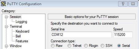
- 表示されたウィンドウで設定を行い、[Serial(シリアル)]ラジオ・ボタンを選択して、事前に確認したCOMポート番号を入力します。ボーレートもあわせて指定します。今回は115,200を入力します
- [Open(開く)]をクリックして、シリアル接続を確立します。ボードが接続されていて、正しいCOMポートが入力されていれば、ターミナル・ウィンドウが開きます。設定が正しくない場合は、アラートが表示されます
- 以上で設定は完了です
近接検出アプリケーション
近接検出アプリケーション
QN9080SIP-DKボードには、あらかじめProximity Reporterデモがプログラム済みで、すぐに使用できます。GATTサーバに加え、次のプロファイルとサービスが実装されています。
- Proximity Profile v1.0.1
- Immediate Alert Service v1.0
- TX Power Service v1.0
- Link Loss Service v1.0.1
- Battery Service v1.0
- Device Information Service v1.1
デモを実行する
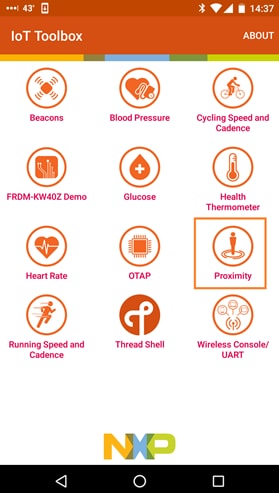
- まず、Google Playまたは App StoreからIoT Toolboxスマートフォン・アプリをダウンロードし、インストールする必要があります。
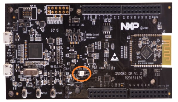
- ボードの電源を入れて
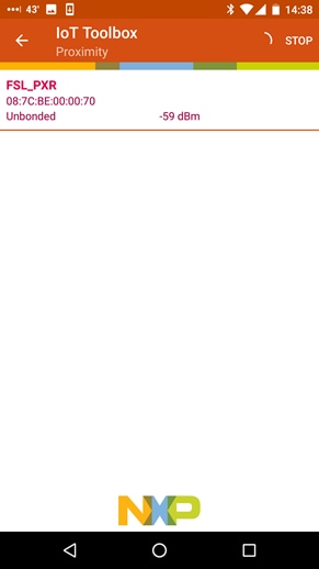
Button1キーを押し、アドバタイジングを開始すると、点滅するライトが赤色に変わります。IoT Toolboxアプリを開いて[Proximity(近接検知)]アイコンをクリックします - 「FSL_PXR」を探してタップし、接続します。
- [Proximity(近接検知)]画面でさまざまなオプションを試します。スマートフォンをボードに近づけたり遠ざけたりして、RSSI値が変化するのを確認します
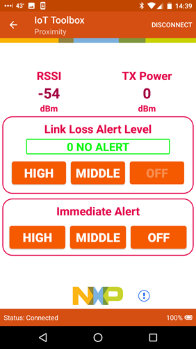
Proximity Reporterアプリケーションの実行方法の詳細については、BLEデモ・アプリケーション・ユーザー・ガイドを参照してください。
設計・リソース
チップに関するドキュメント
ソフトウェア
関連リソース
センサ
豊富な品揃えのNXPセンサ・ソリューションで、世界に目を向けましょう。NXPなら、加速度センサ、圧力センサ、タッチ・センサなど、プロジェクトに適したセンサ・ソリューションを見つけることができます。詳細については、センサをご覧ください。
NFC
NFC (Near Field Communication) は、簡単なタッチだけで周りの世界とセキュアにやり取りできるシンプルで直感的なテクノロジです。NXPのNFCソリューションの詳細については、NFC - Near Field Communicationをご覧ください。
サポート
フォーラム
他のエンジニアとつながり、QN90xx MCUやワイヤレス・コネクティビティ・ソフトウェアを使用した設計に関して専門的なアドバイスを受けることができます。ワイヤレス・コネクティビティ・コミュニティで、コミュニティのディスカッションに参加しましょう。