Getting Started with 15WAUTOS2 EVK Development Board
このドキュメントの内容
-
Out of the Box
-
Get to Know the Hardware
-
Configure Hardware
サインイン 進行状況を保存するには アカウントをお持ちでない方 アカウントを作成する。
お客様の AUTOSAR Qi2ワイヤレス充電トランスミッタ、統合セキュリティ・モジュール搭載
1. Out of the Box
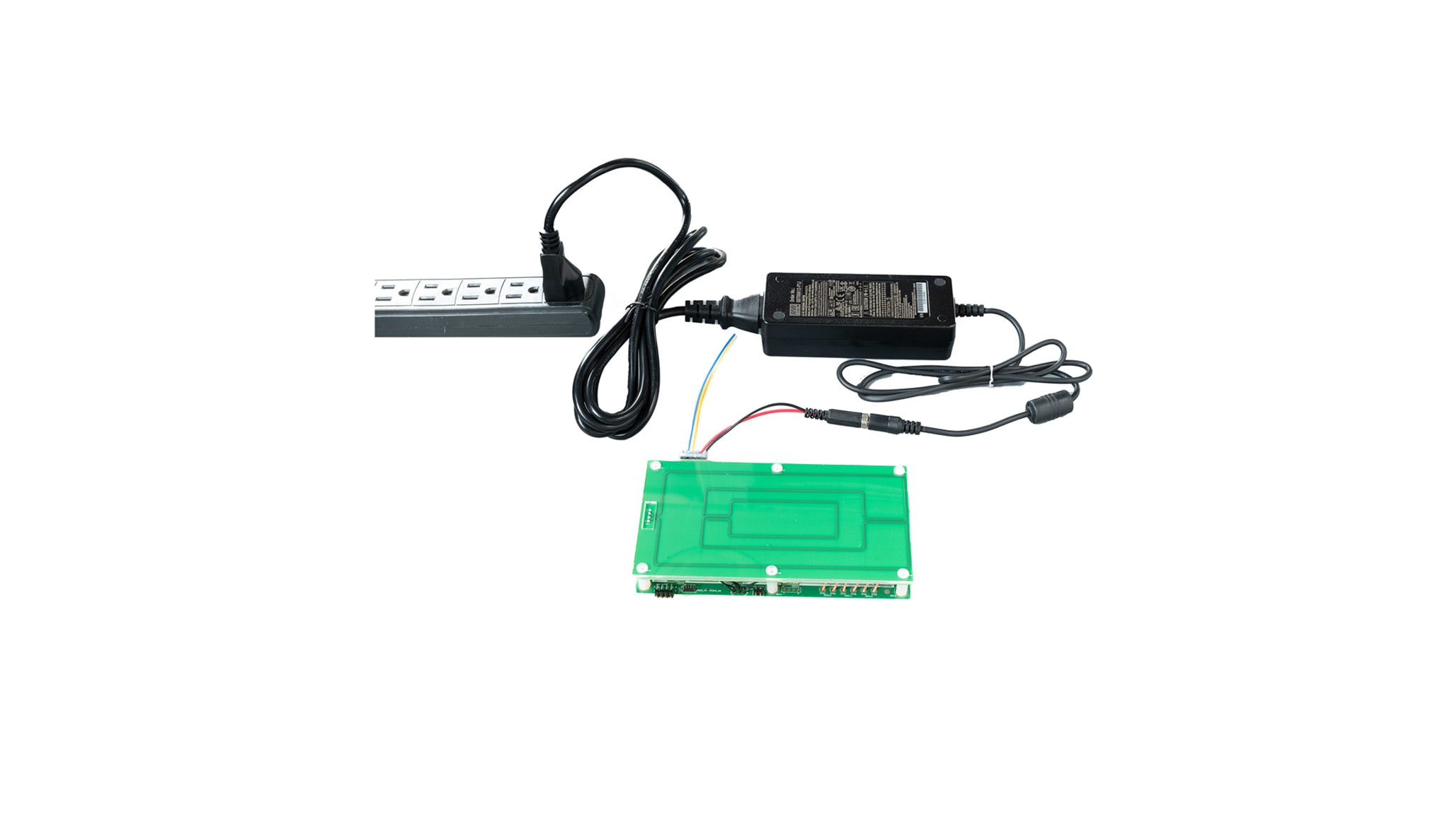
The kit contains all necessary components to enable the 15WAUTOS2 board for wireless charging capability.
1.1 Packing List
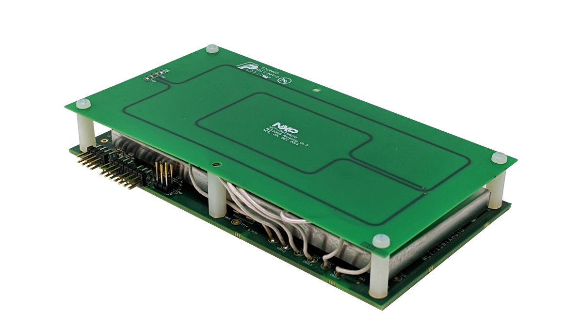
- Printed Wiring Board Assembly (PWA ASSY), WCT-15WAUTOS2
- Extended cable, 2 socket
- HW accessory, universal adaptor
- Power supply 12 vdc 5 a, adapters ce, fcc, pse, ccc, ul, vi approved
1.2 Packing Contents
Wireless Charging Transmitter (WCT) Automotive Reference Design WCT-15WAUTOS2 based on MP-A13 topology, and the contents are:
- Demo board
- Power supply connector cable
- Power supply 12 V/3 A
2. Get to Know the Hardware
2.1 Get to Know the Hardware
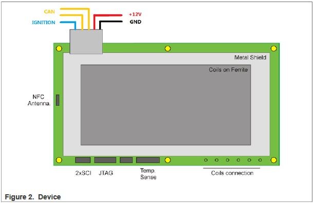
The WCT board is connected to the system by the main power connector. It comprises of the automotive battery connection (red wire = +12 V line, black wire = GND line), the CAN connection (yellow wires), and the IGNITION (blue wire). The connectors at the bottom edge of the board provide JTAG connection for programming and debugging, 2xSCI for the FreeMASTER tool connection for the debug option and console connection and the temperature connector and backup touch sense connector are placed at the edge of the board. The thermal resistor circuits can be used to develop the temperature sensing and protection.
3. Configure Hardware
3.1 Setup
To set up the hardware for FreeMASTER and Console communication, perform the following steps:
- Find two UART-to-USB adapter boards, and successfully install this UART-to-USB device driver on the computer. The virtual serial port on the computer should work well.
- Plug the USB-UART converting board to SCI connector
J5according to the SCH signal pin position. The two channels of UART are for different purposes: FreeMASTER and Console.