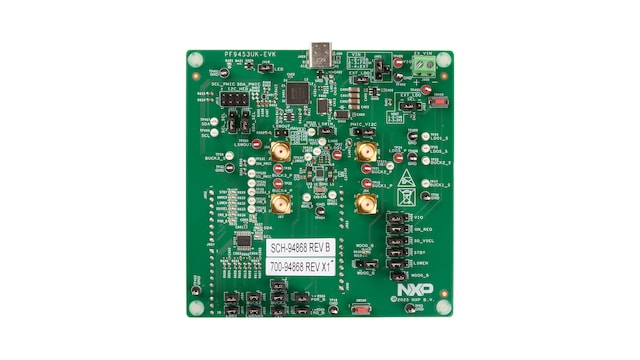
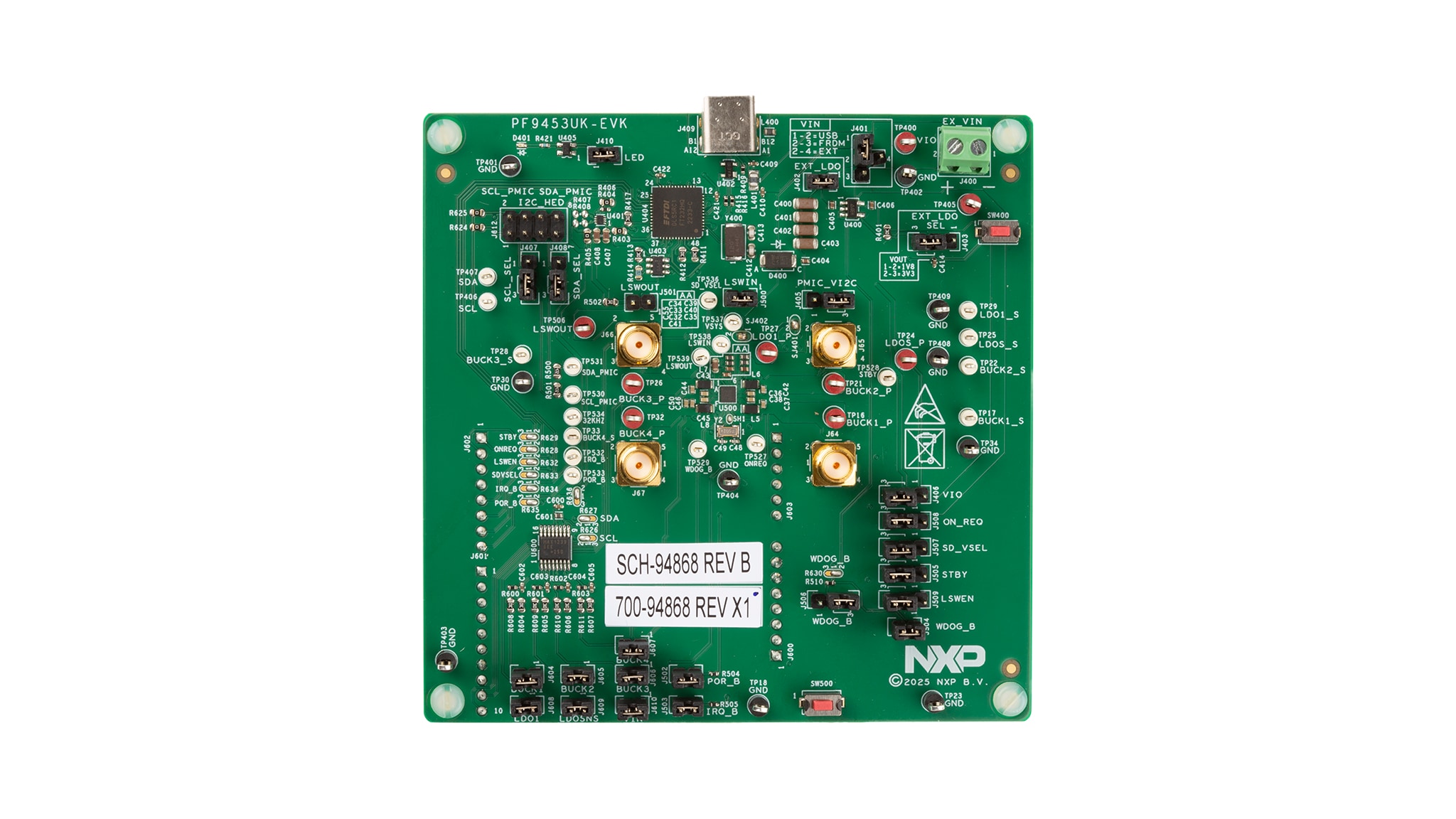
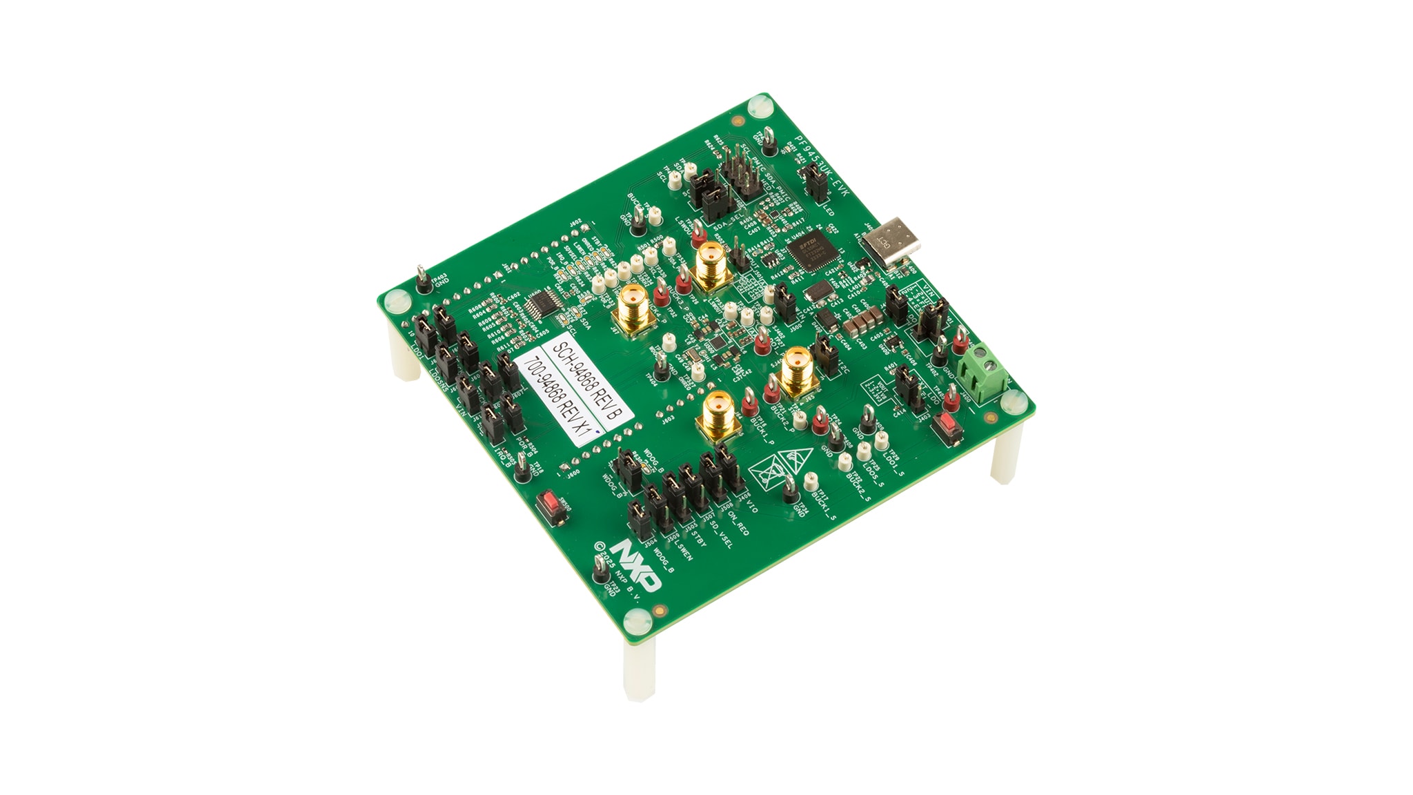
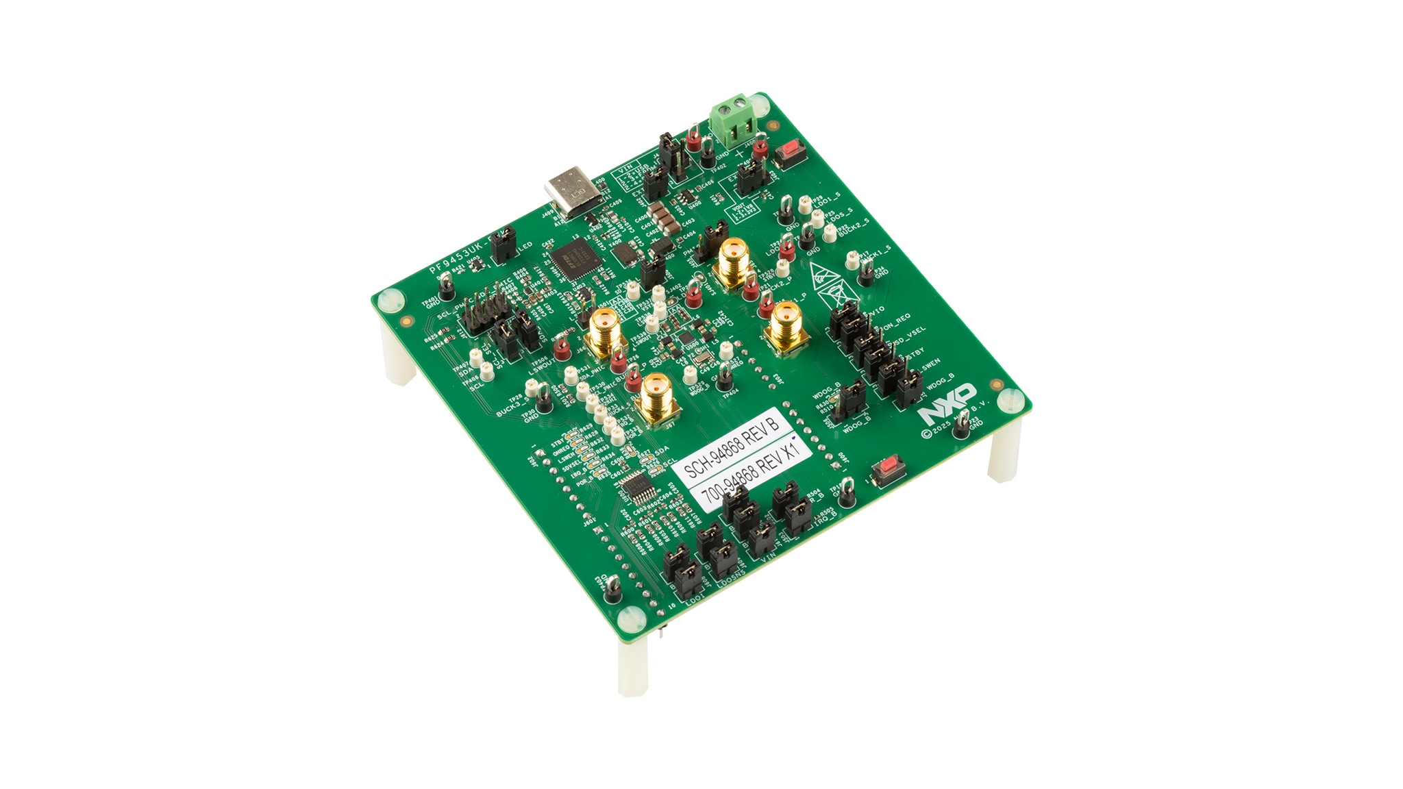
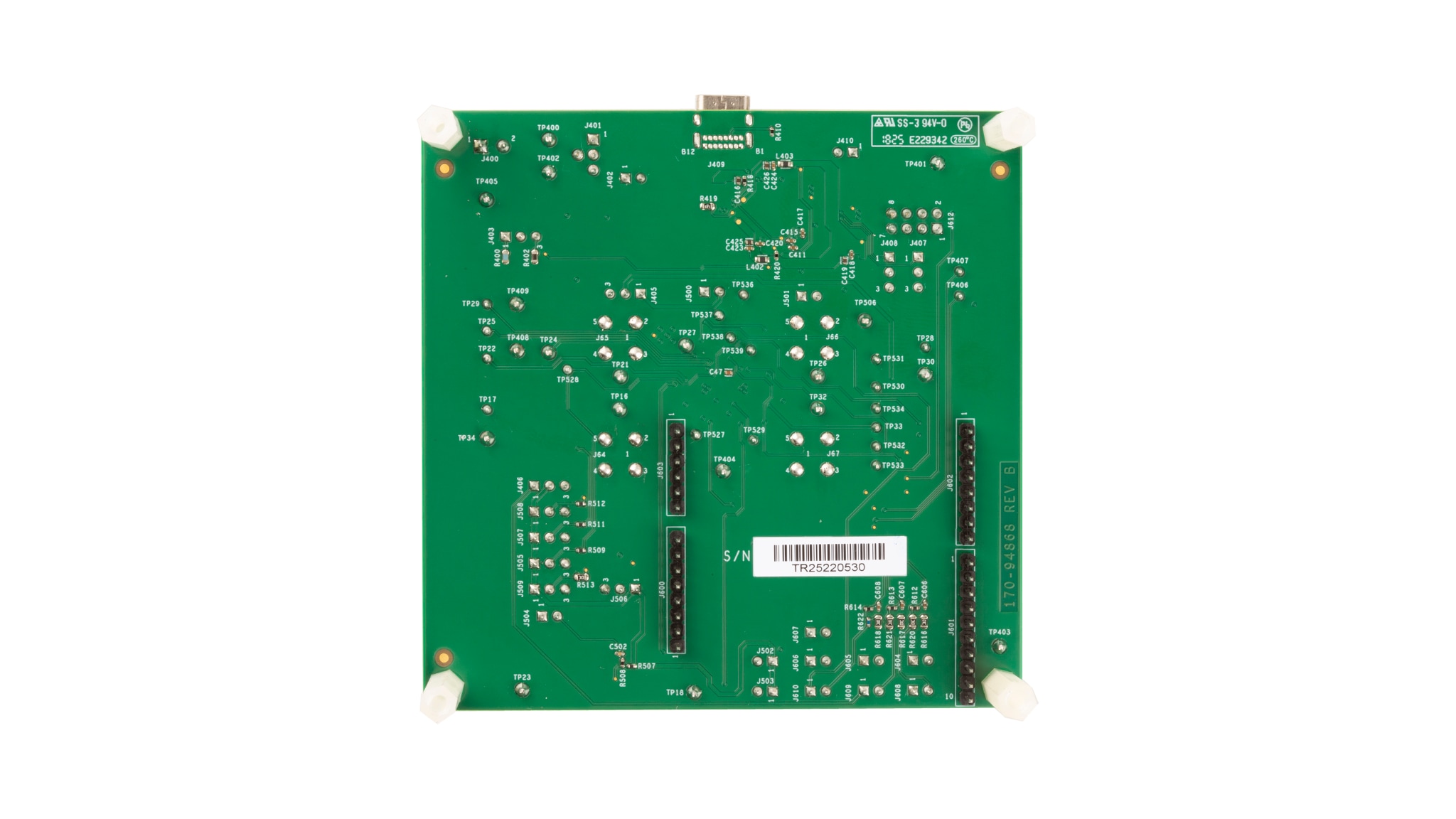
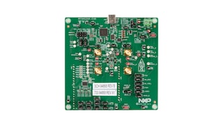
PF9453 WLCSP Low Power Multi-Rail PMIC Evaluation Board

  • This page contains information on a preproduction product. Specifications and information herein are subject to change without notice. For additional information please contact your sales representative.

画像にカーソルを合わせると拡大表示されます。

ブロック図

PF9453

PF9453 Block Diagram

対応製品

パワーマネージメント

PMIC

Features

Four Buck Regulators

  • BUCK1: 0.6 V to 3.775 V, 25 mV step, 2000 mA
  • BUCK2: 0.6 V to 2.1875 V, 12.5 mV step, 2700 mA (QFN) / 2000 mA (WLCSP)
  • BUCK3: 0.6 V to 3.775 V, 25 mV step, 2000 mA
  • BUCK4: 0.6 V to 3.775 V, 25 mV step, 2500 mA
  • Dynamic Voltage Scaling on BUCK2
  • Monitor fault condition

Three Linear Regulators

  • LDO_SNVS, always-on, 1.2 V to 3.4 V in QFN or 0.8 V to 3.0 V in WLCSP with 25 mV step, 10 mA
  • LDO1, 0.8 V to 3.3 V with 25 mV step, 250 mA, voltage selection through SD_VSEL pin
  • LDO2 (QFN only), 0.5 V to 1.95 V with 25 mV step, 200 mA

Power Control IO

  • Power ON/OFF control
  • Standby/Run mode control
  • Watchdog reset input

ESD Protection

  • Human body model (HBM): ± 2000 V
  • Charged device model (CDM): ± 500 V

System Features

  • One 400 mA load switch with a built-in active discharge resistor and GPIO/I²C control
  • 32.768 kHz crystal oscillator driver and buffer output
  • Flexible power ON/OFF sequence, one time programmable (OTP) device configuration
  • Built-in active discharge resistor
  • Fm+ 1 MHz I²C Interface

ドキュメント

クイック・リファレンス ドキュメンテーションの種類

1 ドキュメント

コンパクトリスト

設計・リソース

デザイン・ファイル

クイック・リファレンス 設計・ファイルの種類.

2 設計・ファイル

サポート

お困りのことは何ですか??