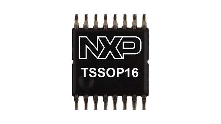
4-Bit Multiplexed/1-Bit Latched 5-Bit I²C EEPROM DIP Switch

製品画像を見る

製品詳細

セクションを選択:

ブロック図

PCA8550 Block Diagram

PCA8550 Block Diagram

Features

Key Features

  • 4-bit 2-to-1 multiplexer, 1-bit latch DIP switch
  • 5-bit internal non-volatile register
  • Override input forces all outputs to logic 0
  • Internal non-volatile register write/readable via I2C-bus
  • Write-protect pin enables/disables I2C writes to register
  • 2.5 V multiplexed outputs
  • 3.3 V non-multiplexed output (latched)
  • 5 V tolerant inputs
  • Useful for "jumperless" configuration of PC motherboards
  • Designed for use in Pentium Pro/Pentium II systems

ドキュメンテーション

クイック・リファレンス ドキュメンテーションの種類.

1-5 の 12 ドキュメント

全て表示

設計・リソース

設計・ファイル

5 設計・ファイル

  • シミュレーションとモデル

    PCA8550DB IBIS model

  • シミュレーションとモデル

    PCA8550PW IBIS model

  • シミュレーションとモデル

    PCA8550D IBIS model

  • シンボルおよびフットプリント

    PCA8550PW-TSSOP16-CAD Symbol and PCB Footprint – BXL File

  • シンボルおよびフットプリント

    PCA8550DB-SO16-BXL-CAD Symbol and PCB Footprint – BXL File

エンジニアリング・サービス

2 エンジニアリング・サービス

本製品をサポートするパートナーの一覧は、 パートナーマーケットプレイス.

サポート

お困りのことは何ですか??