Power Supply Design Tools and Resources
このドキュメントの内容
-
Out of the Box
-
Get Hardware
-
Plug It In
サインイン 進行状況を保存するには アカウントをお持ちでない方 アカウントを作成する。
お客様の TEA2096DB2201
1. Out of the Box
1.1 Box Contents
- TEA2096DB2201 add-on board
1.2 Required Equipment
- AC main source
- Power analyzer
- Electronic load
- Oscilloscope for observing operation behavior
- Current probe
1.3 Additional Hardware
- An existing switch mode power supply board with a resonant topology
2. Get Hardware
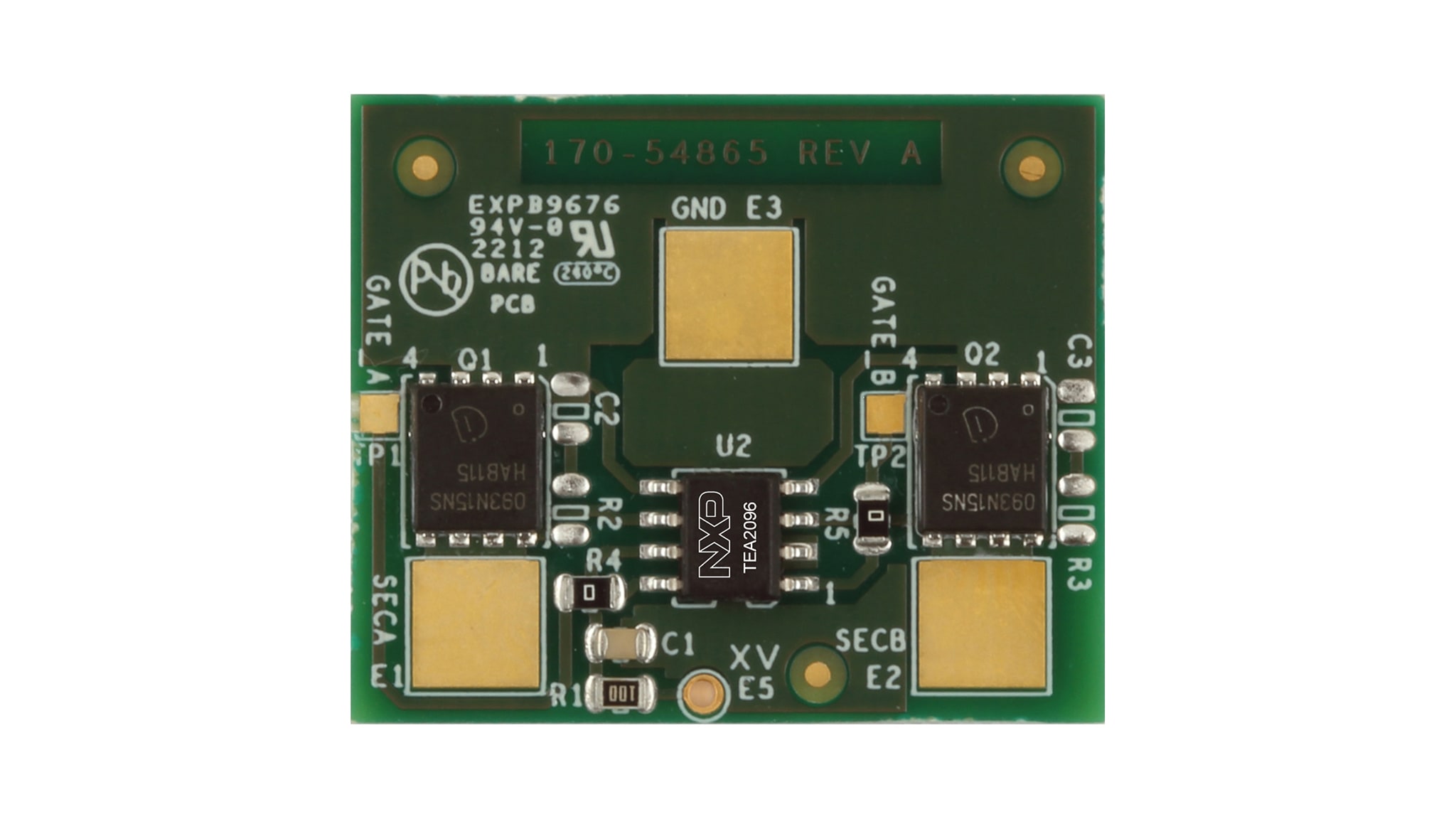
2.1 Overview
The TEA2096DB2201 add-on evaluation board contains a TEA2096T SR controller in an SO-8 package and two 150 V / 9.3 mΩ MOSFETs in PD-TSON-8 package.
The TEA2096T is a dedicated controller IC for synchronous rectification on the secondary side of resonant converters. It incorporates two stages for sensing and driving the SR MOSFETs, which rectify the outputs of the central tap secondary transformer windings. The TEA2096T has a drain-source voltage rating of 200 V.
These features make the evaluation board suitable for resonant applications with an output voltage of up to 60 V.
3. Plug It In
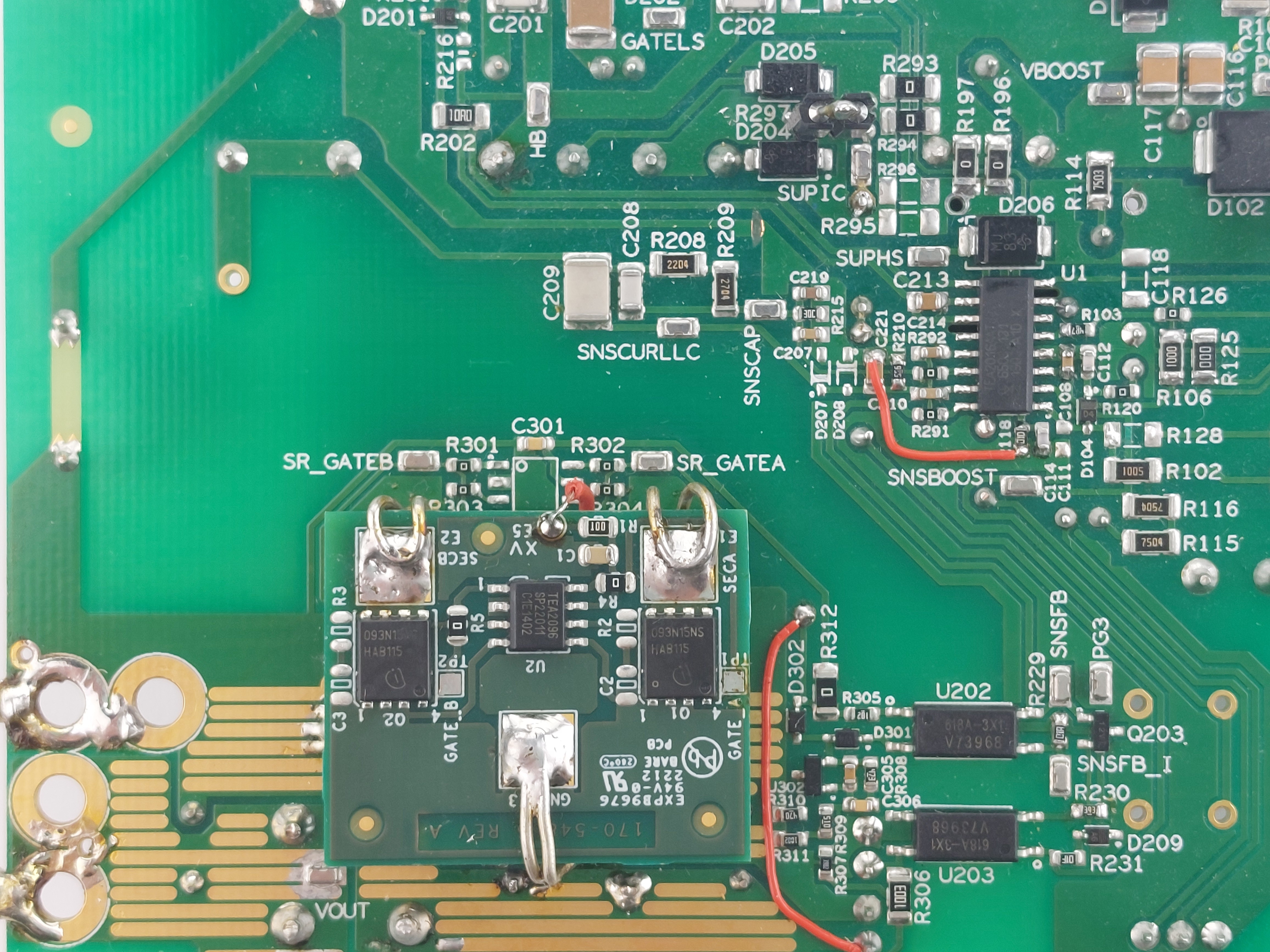
3.1 Connecting the Board to an Existing SMPS
Connect the pads SECA and SECB to the secondary outputs of the transformer. Connect the GND pad to the power ground of the main board. Use thick wires for the SECA, SECB and GND connections, because the currents in these tracks can be high.
For output voltages up to 38 V, the XV connection can be connected to the Vout of the main board. For output voltages of more than 38 V, a series regulator is required to reduce the supply voltage of the TEA2096T to below 38 V. When a series regulator is used, a trade-off can be made between the dissipation in the regulator and the dissipation in the TEA2096T.
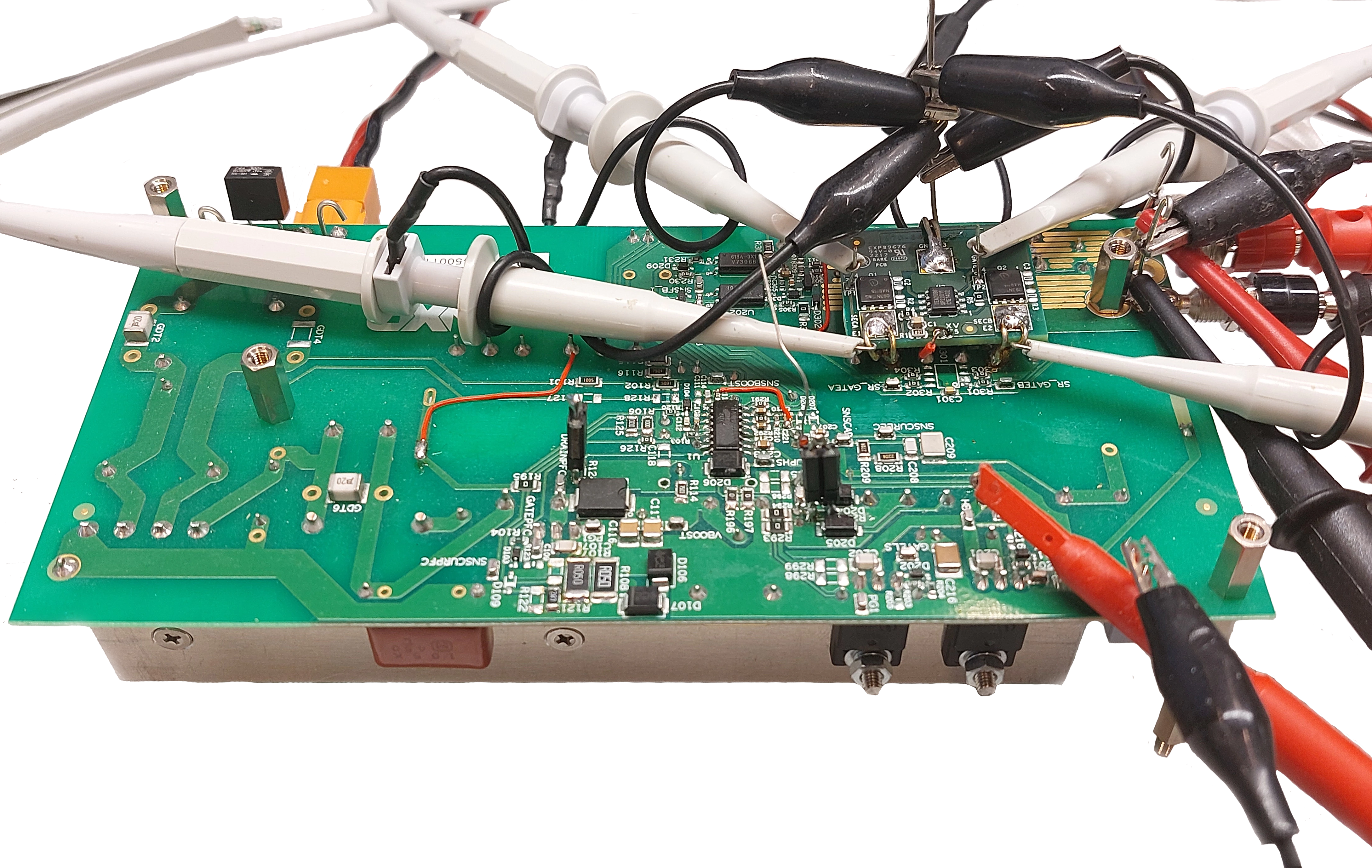
3.2 Connecting the Oscilloscope
The operation of the TEA2096DB2201 in the power supply can evaluated by measuring:
GATE_AGATE_BSECASECB- The current through the
GNDconnection with a current probe - The Half Bridge node of the resonant converter
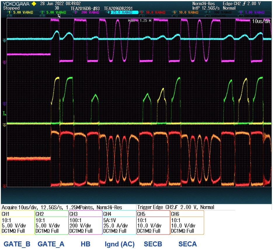
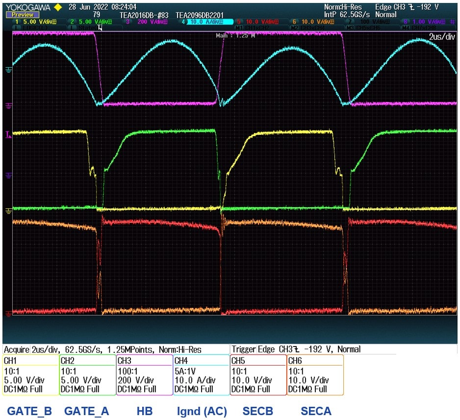
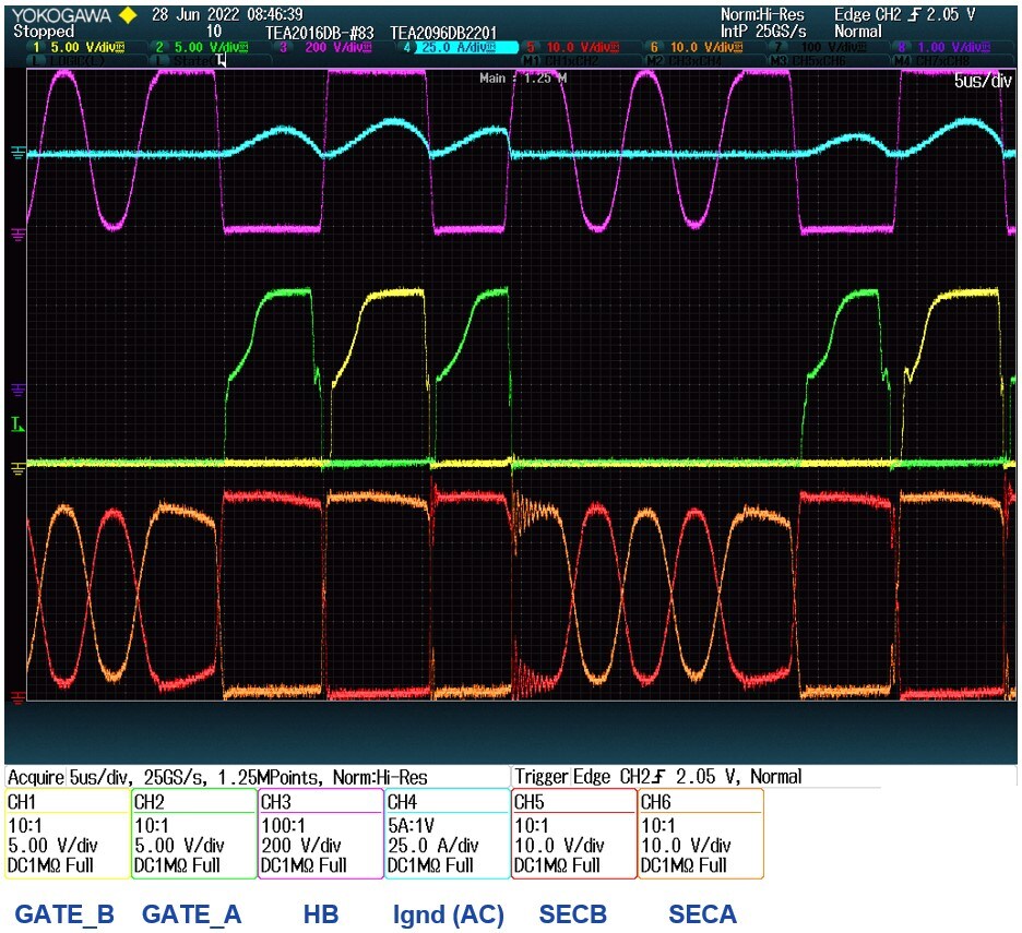
3.3 Oscilloscope Signals
Operation in a resonant converter with a TEA2016T or a TEA2017T at high load.
Operation in a resonant converter with a TEA2016T or a TEA2017T at low load.
Operation in a resonant converter with a TEA2016T or a TEA2017T at no-load.