EVBMA7318-SPI評価ボードのスタート・ガイド
このドキュメントの内容
-
パッケージの内容
-
ハードウェアの入手
-
ハードウェアの構成
サインイン 進行状況を保存するには アカウントをお持ちでない方 アカウントを作成する。
お客様の EVBMA7318-SPI
1. パッケージの内容
NXPのアナログ製品開発ボードは、NXP製品の評価を目的とした使いやすいプラットフォームです。さまざまなアナログ・ソリューション、ミックスド・シグナル・ソリューション、パワー・ソリューションに対応しています。実績のある大容量テクノロジを使用したモノリシック集積回路 (IC) およびシステム・イン・パッケージ (SiP) デバイスを搭載しています。NXP製品は、最先端システムへの電源供給において、より長いバッテリー寿命、より小さいフォーム・ファクタ、より少ない部品数、より低いコスト、より優れたパフォーマンスを実現します。
このページでは、EVBMA7318-SPI評価ボードをセットアップして使用する手順について説明します。
1.1 キットの内容と同梱物一覧
EVBMA7318-SPIキットには以下のものが含まれています。
- EVBMA7318-SPIボード
- バッテリー・シミュレーション・ケーブル x 1:バッテリー・セル・コントローラ (BCC) への電源供給。各セルを直列抵抗でシミュレートします
- 電流測定ケーブル x 1:シャントおよびその校正NTCに接続します
- トランス物理層 (TPL) デイジー・チェーン・ケーブル x 1:TPLで他のボードと通信するためのケーブル
- シリアル・ペリフェラル・インターフェース (SPI) 通信ケーブル x 2:SPIでUMFT4222EV/コントローラ・ボードと通信するためのケーブル
- デバッグ・ケーブルとUMFT4222EVボード x 1
1.2 追加ハードウェア
デバイスの評価に追加のハードウェアは必要ありませんが、電流容量500 mAの24 V直流 (VDC) 電源または4~18セルのバッテリー・パックの使用をお勧めします。このキットの作業をする際は、キットの内容物のほかに以下のハードウェア(オプション)を使用すると役立ちます。
- 外部シャントおよびシャントに接続可能な電流源
- バッテリー・エミュレータ・ボードBATT-7318EMU(アクセス・リンク:BATT-7318EMU)
- 5 VDC電源(電流容量500 mA)
1.3 最小システム要件
この評価ボードにはWindows PCが必要です。システムが最小仕様(32ビット版または64ビット版のWindows® 11/10/8/7、Windows XP、またはVista)を満たしていることを確認してください。最小仕様を満たすことで、この評価ボードの使用時に信頼性の高い性能が確保されます。
1.4 ソフトウェア
この評価ボードで作業を開始する前に、ソフトウェアをインストールする必要があります。以下のプログラムをインストールしてください。
- グラフィカル・ユーザー・インターフェース (GUI):ScriptGUI V3.5+
- BMA7318用のScriptGUIプラグイン
記載されているすべてのソフトウェアは、評価ボードの情報ページ (EVBMA7318-SPI) またはNXPのGUIページ (SWBMS-ScriptGUI-D) から入手できます。
2. ハードウェアの入手
2.1 ボードの特長
EVBMA7318-SPI評価ボードの特長は次のとおりです。
- 分散型バッテリー・マネジメント・システム (BMS) アーキテクチャ
- ボードあたり1つのBMA7318
- 最大18個のバッテリー・セルの電圧を高精度で測定可能
- 10個の温度検知チャネル
- TPL絶縁通信
- コントローラへのSPI通信と、データ転送のためのSPI2TPLブリッジ
- 最大300 mAのセル・バランシング電流
- 高精度または高速モードの電流測定チャネル
- 高い電磁環境適合性 (EMC) 性能
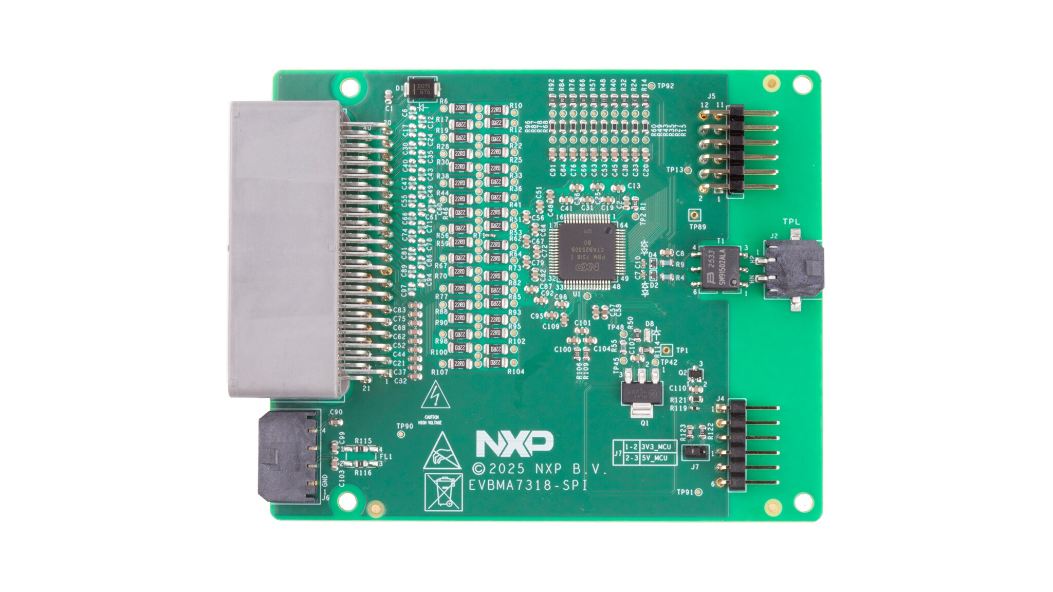
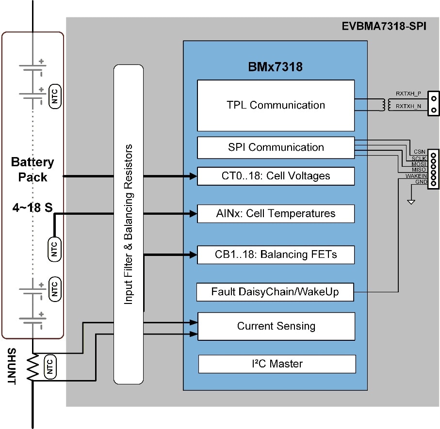
2.2 ボードの説明
このボードには、1つのBMA7318デバイスが搭載されています。図に示すように、このボードはSPIを介してコントローラ・ボードまたはコントローラPCと通信し、トランス絶縁を使用したTPLを介して他のセル・モニタリング・ユニット (CMU) ボードと通信します。各ボードは、4~18セルのリチウムイオン・バッテリーを測定します。このボードは、9 VDC~90 VDCの電源で動作します。
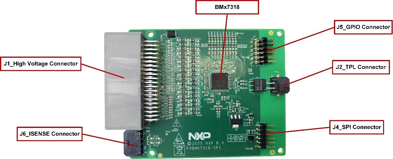
2.3 ボードのコンポーネント
図2にボード上の重要なコンポーネントを示し、表1にこれらのコンポーネントの詳細を示します。
| 番号 | デバイス | 説明 |
|---|---|---|
| 1 | BMA7318FAIAE | 18チャネルのリチウムイオン・バッテリー・セル・コントローラIC |
2.4 コネクタ
| ピン | 名称 | 説明 |
|---|---|---|
| 1 | NC | 無接続 |
| 2 | NTC7 | 温度検知用に外部NTC抵抗に接続 |
| 3 | NTC6 | 温度検知用に外部NTC抵抗に接続 |
| 4 | NTC5 | 温度検知用に外部NTC抵抗に接続 |
| 5 | NTC4 | 温度検知用に外部NTC抵抗に接続 |
| 6 | NTC3 | 温度検知用に外部NTC抵抗に接続 |
| 7 | NTC2 | 温度検知用に外部NTC抵抗に接続 |
| 8 | NTC1 | PCB温度検知用に内部NTC抵抗に接続済み |
| 9 | GND | BCCのグランド |
| 10 | C1P | セル1電圧検知ポイント |
| 11 | C3P | セル3電圧検知ポイント |
| 12 | C5P | セル5電圧検知ポイント |
| 13 | C6Pb | セル6電圧検知ポイントb |
| 14 | C8P | セル8電圧検知ポイント |
| 15 | C10P | セル10電圧検知ポイント |
| 16 | C12Pa | セル12電圧検知ポイントa |
| 17 | C13P | セル13電圧検知ポイント |
| 18 | C15P | セル15電圧検知ポイント |
| 19 | C17P | セル17電圧検知ポイント |
| 20 | PVWR | BCC用電源 |
| 21 | NC | 無接続 |
| 22 | NTC8 | 温度検知用に外部NTC抵抗に接続 |
| 23 | NTC9 | 温度検知用に外部NTC抵抗に接続 |
| 24 | GND | NTC抵抗のグランド |
| 25 | GND | NTC抵抗のグランド |
| 26 | GND | NTC抵抗のグランド |
| 27 | GND | NTC抵抗のグランド |
| 28 | GND | NTC抵抗のグランド |
| 29 | GND | NTC抵抗のグランド |
| 30 | COM | セル0電圧検知ポイント |
| 31 | C2P | セル2電圧検知ポイント |
| 32 | C4P | セル4電圧検知ポイント |
| 33 | C6Pa | セル6電圧検知ポイントa |
| 34 | C7P | セル7電圧検知ポイント |
| 35 | C9P | セル9電圧検知ポイント |
| 36 | C11P | セル11電圧検知ポイント |
| 37 | C12Pb | セル12電圧検知ポイントb |
| 38 | C14P | セル14電圧検知ポイント |
| 39 | C16P | セル16電圧検知ポイント |
| 40 | C18P | セル18電圧検知ポイント |
| ピン | 名称 | 説明 |
|---|---|---|
| 1 | H_INOUT+ | TPL_Hツイスト・ワイヤのプラス側 |
| 2 | H_INOUT- | TPL_Hツイスト・ワイヤのマイナス側 |
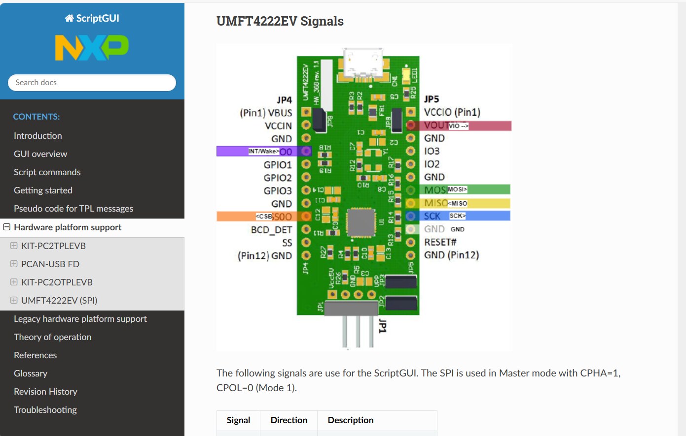
| ピン | 名称 | 説明 |
|---|---|---|
| 1 | WAKEIN_CON | ウェイクアップ入力 |
| 2 | CSN | コントローラからのSPIチップ・セレクト入力 |
| 3 | MOSI | コントローラからのSPIターゲット・データ入力 |
| 4 | MISO_CON | コントローラへのSPIターゲット・データ出力 |
| 5 | SCLK | コントローラからのSPIクロック入力 |
| 6 | GND | SPIのGND |
| ピン | 名称 | 説明 |
|---|---|---|
| 1 | GPIO0 | GPIO0デバッグ |
| 2 | GPIO9/ALARMOUT | GPIO9/ALARMOUTデバッグ |
| 3 | GPIO1 | GPIO1デバッグ |
| 4 | GPIO8 | GPIO8/SPIステータス表示デバッグ |
| 5 | GPIO2 | GPIO2デバッグ |
| 6 | GPIO7 | GPIO7/OCOUTデバッグ |
| 7 | GPIO3 | GPIO3デバッグ |
| 8 | GPIO6 | GPIO6デバッグ |
| 9 | GPIO4 | GPIO4デバッグ |
| 10 | GPIO5 | GPIO5デバッグ |
| 11 | GND | GPIOのGND |
| 12 | GND | GPIOのGND |
| ピン | 名称 | 説明 |
|---|---|---|
| 1 | GND | NTCのGND |
| 2 | ISENSE- | 電流検知入力_マイナス側 |
| 3 | ISENSE+ | 電流検知入力_プラス側 |
| 4 | NTC_SHUNT | 温度検知用にシャントNTC抵抗に接続 |
3. ハードウェアの構成
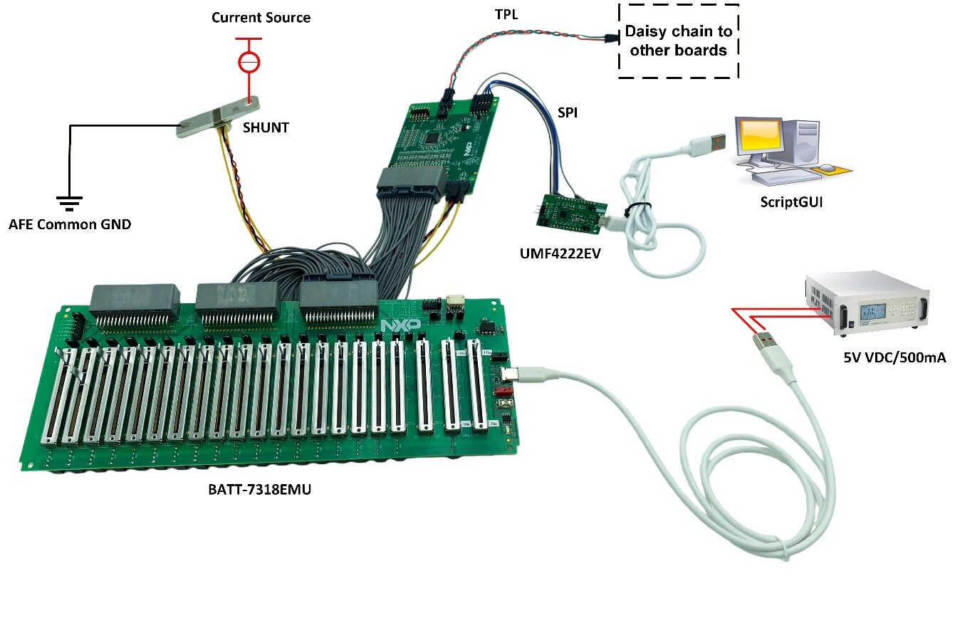
図3および図4は、開発ボード、電源、Windows PCワークステーションを含む一般的なハードウェア構成を示しています。
3.1 バッテリー・シミュレーション・ケーブルに基づいたセットアップ
このセットアップでは、ScriptGUIを使用します。また、EVBMA7318-SPIをコントローラPCに接続するには、UMFT4222EVが必要です。EVBMA7318-SPIはScriptGUIを使用してデバッグします。
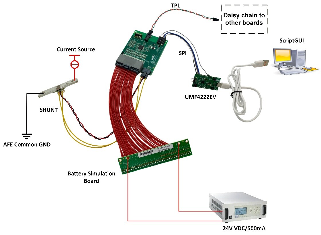
このセットアップは、BMA7318FAIAEをベースにしたEVBに適しています。UMFT4222EVの接続方法については、ScriptGUIのヘルプ・ドキュメントを参照してください(図4を参照)。
設計・リソース
その他の参考情報
- EVBMA7318-SPI - EVBMA7318-SPI—このボードの詳細情報(ドキュメント、ダウンロード、ソフトウェア、ツールなど)
- BMA7318-BMI7318-BMA7518 - BMx7318—18チャネル・リチウムイオン・バッテリー・セル・コントローラIC、BMx7318の詳細情報。