Fast-Track Motor Control Designs
このドキュメントの内容
-
Plug It In
-
Get Software
-
Build, Run
サインイン 進行状況を保存するには アカウントをお持ちでない方 アカウントを作成する。
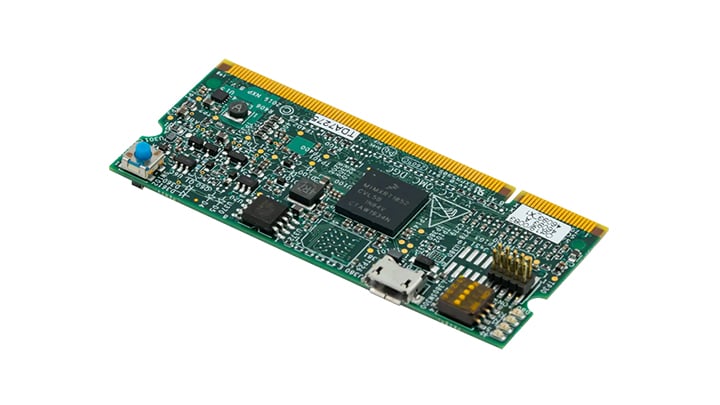
お客様の Quad Motor Control Development Platform
Plug It In
Learn the basics to run your development platform boards, daughter board and digital board. Get up and running with your multi-motor control designs.
1.1 Kit Content
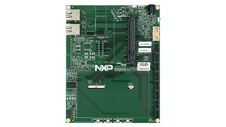
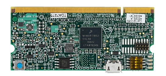
1.3 Connection Diagram
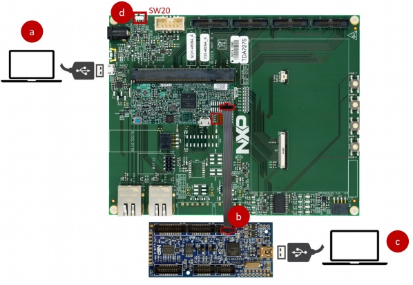
- Attach a USB cable from the computer to the digital board
-
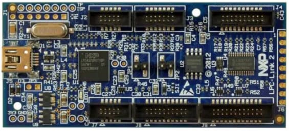
Connect the LPC-Link 2 board (
J7 jumper) to the daughter board using aJTAGcable in theSWDconnector - Attach a USB cable from the computer to the LPC-Link 2 board
- Power on the board using
SW20
After importing and building the project, we need to prepare hardware setup to program the NXP quad motor-control application using the LPC-Link 2 debug probe.
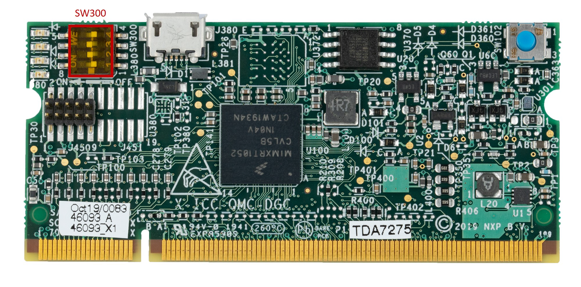
The daughter board allows the selection of the internal boot or serial
downloader boot modes of the i.MX RT1050 crossover processor using the
SW300 DIP switch. Select the internal boot mode configuring the
SW300 DIP switch as described in the next table.
| Switch | State |
|---|---|
|
1 |
OFF |
|
2 |
ON |
|
3 |
ON |
|
4 |
OFF |
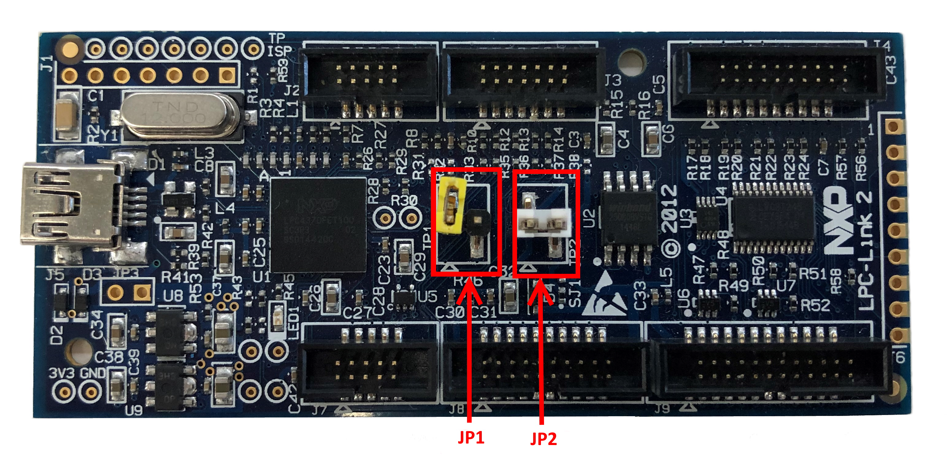
Configure LPC-Link 2 board jumpers.
- JP1 open: boot USB DFU
- JP2 closed: buffers power by LPC-Link 2
Get Software
2.1 MCUXpresso Integrated Development Environment (IDE)
The MCUXpresso IDE brings developers an easy-to-use Eclipse-based development environment for NXP® MCUs based on Arm® Cortex® -M cores, including LPC and including LPC, Kinetis and i.MX RT crossover MCUs.
MCUXpresso Integrated Development Environment (IDE)
2.3 FreeMASTER Run-Time Debugging Tool
FreeMASTER is a user-friendly real-time debug monitor and data visualization tool that enables runtime configuration and tuning of embedded software applications.
FreeMASTER Run-Time Debugging Tool
Build, Run
3.1 Get the i.MX RT1050 SDK
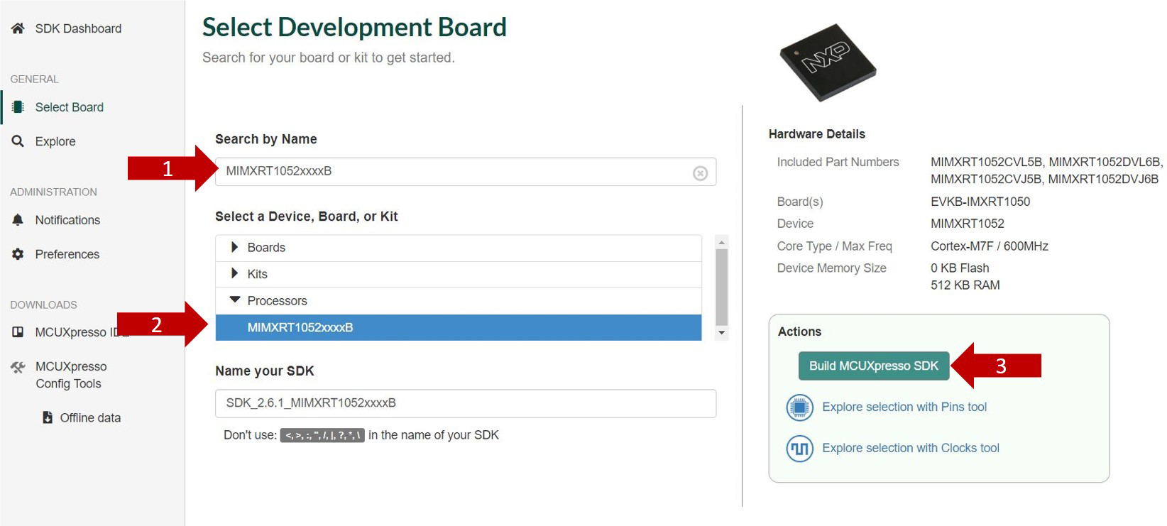
In the SDK Builder, you will be asked to sign in with your NXP account (if you don't have one yet, click on Register Now), type your credentials in the fields and then click on Sign in.
Type MIMXRT1052xxxxB on the text box (1), select it (2) in the drop-down list and click (3) Build MCUXpresso SDK button as shown.
3.2 Accept Terms and Download
Click Download SDK button and accept the software terms and conditions.
3.3 Install the i.MX RT1050 SDK in MCUXpresso
Open MCUXpresso, (1) select the Installed SDKs tab and (2) drag and drop the compressed SDK folder to its area. A warning window should pop up.
The i.MX RT1050 crossover processor SDK should now be listed in the Installed SDK tab.
3.4 Open the Quad Motor Control Project from File System
Download the NXP quad motor-control application MCUXpresso project from the Tools and Software section.
Browse the NXP quad motor-control application MCUXpresso project as shown in the next figure.
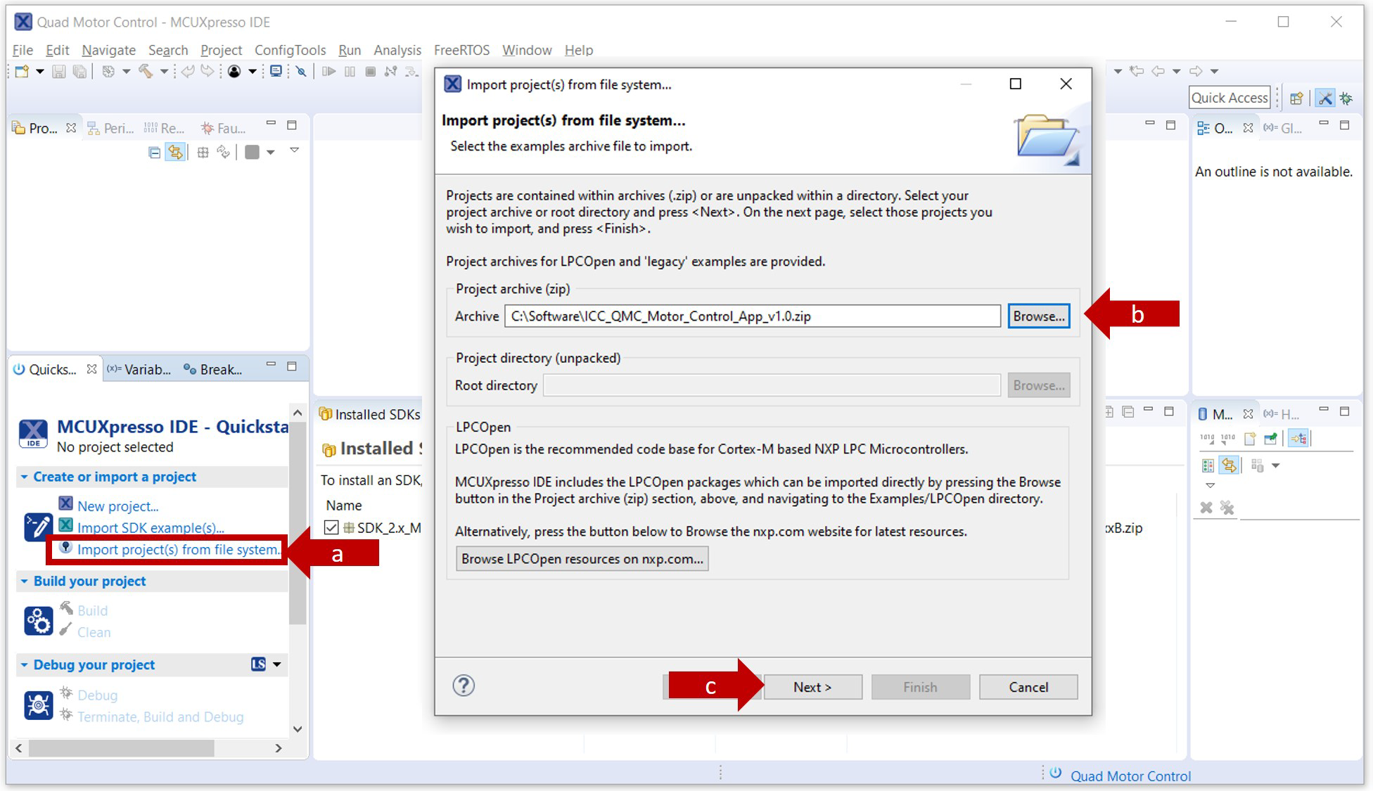
Select the project example and click the Finish button. The project selected should now be visible in your MCUXpresso worskpace.
3.5 Building the Project
Click the Build button in the MCUXpresso quick start panel to compile the project.
Check in the MCUXpresso console that the project build finished successfully and without errors.
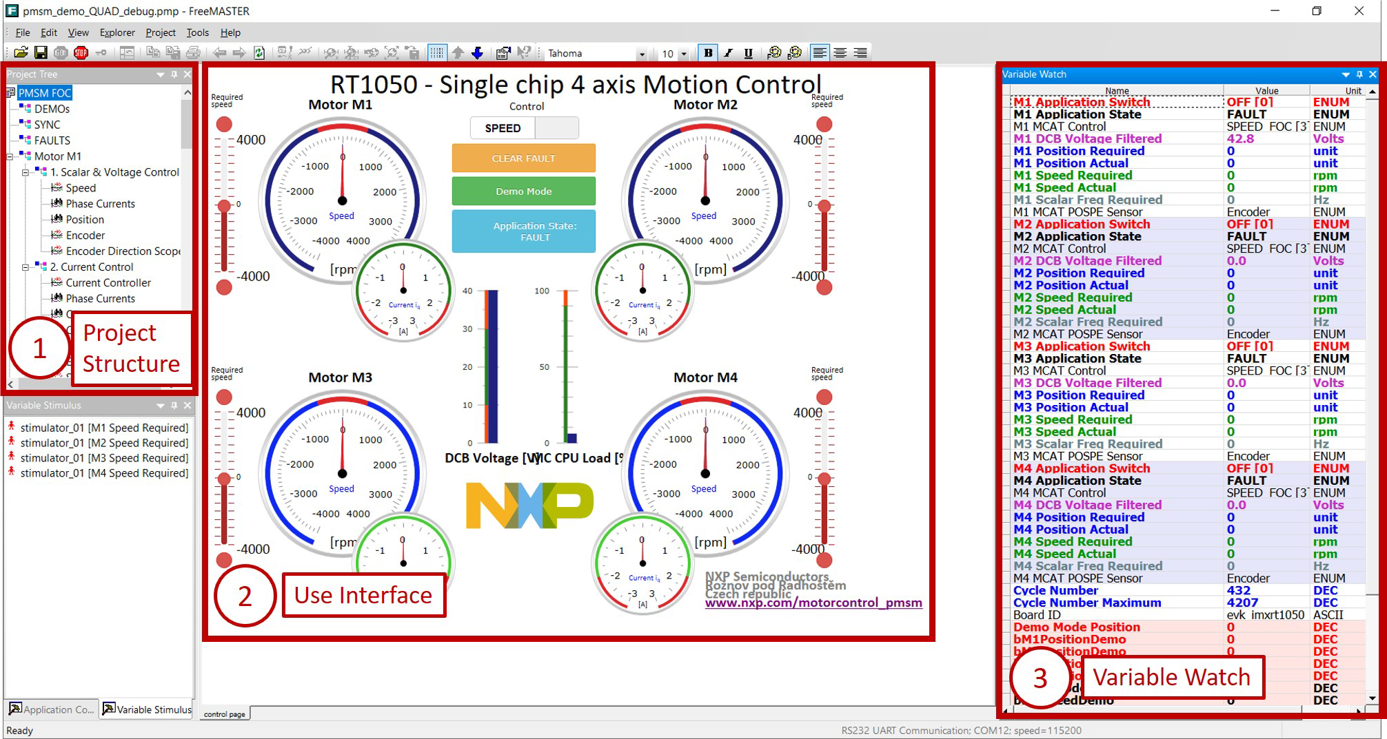
RT1050 - Single Chip 4 Axis Motion Control
This section details how to run the FreeMASTER project provided as part of the NXP quad motor-control application.
Note: FreeMASTER run-time debugging tool installation is required. If you do not have it installed in your laptop, begin the download by clicking the link from Section 2.
To run the NXP quad motor-control FreeMASTER project, follow these instructions:
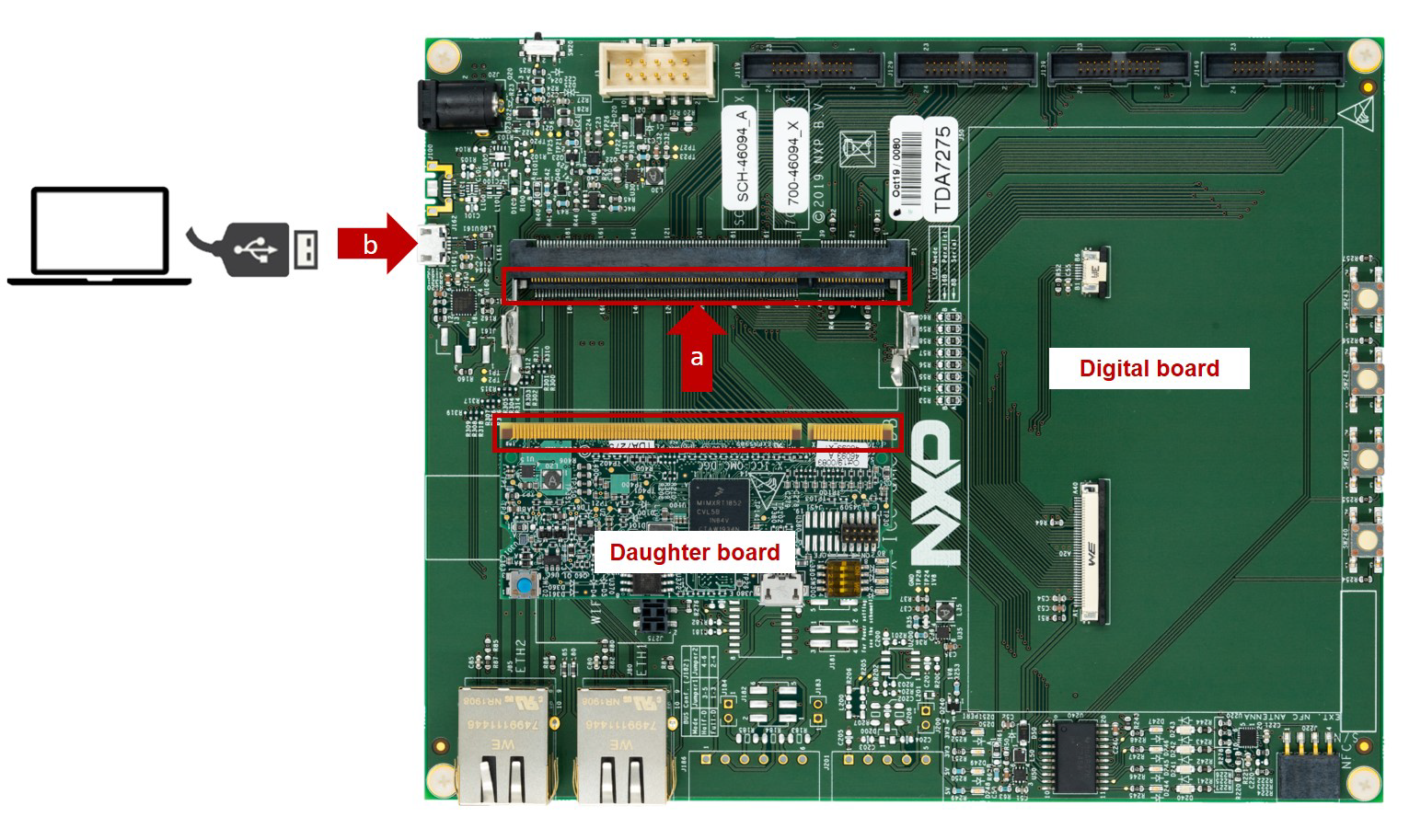
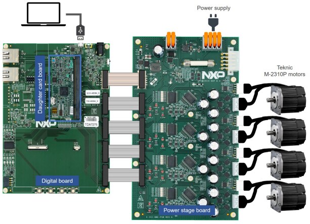
- Connect the NXP quad motor-control development platform to the computer as shown in the next figure.
- Attach the daughter board to the digital board using the edge connector
- Attach a USB cable from the computer to the digital board
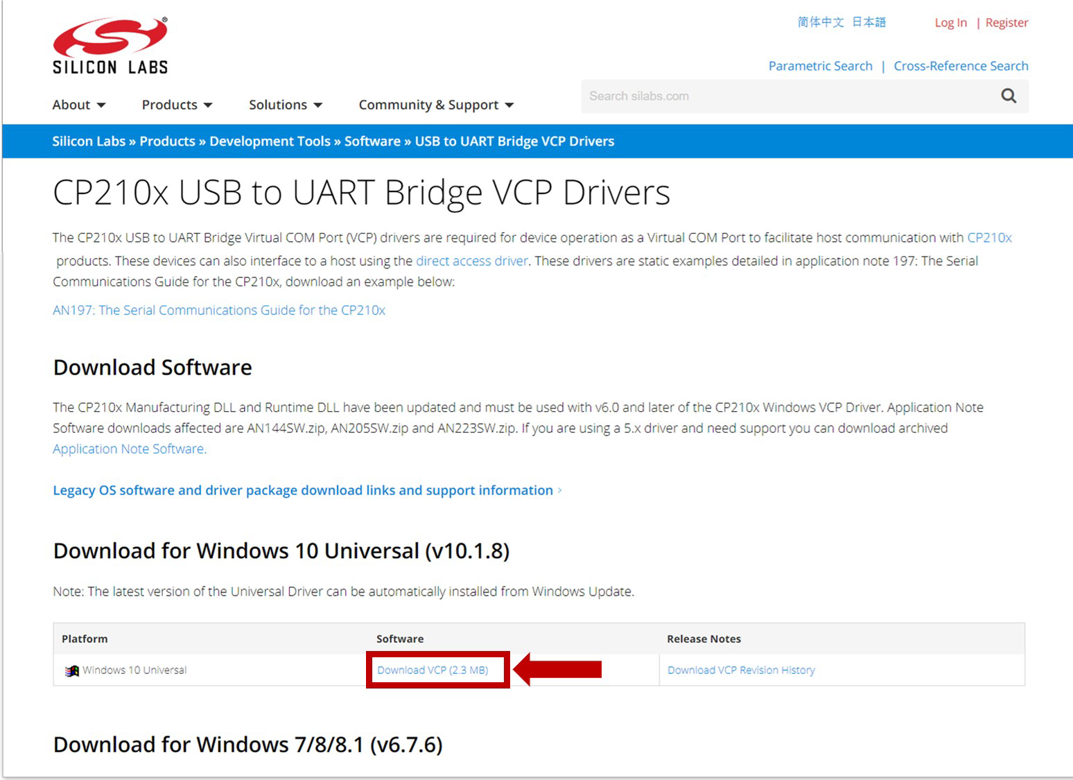
- Download and install the USB to UART Bridge VCOM driver, required to communicate with the digital board. Go to Silabs and download the driver from this link.
- Unplug and plug the digital board from the computer. Open your Device Manager, and check that your board is recognized and assigned to two port numbers (COMxx)
- Write down the assigned port number (COMxx) as it is needed in the next steps
- Download the FreeMASTER project from www.nxp.com/quadmotorcontrol, under the Tools and Software section
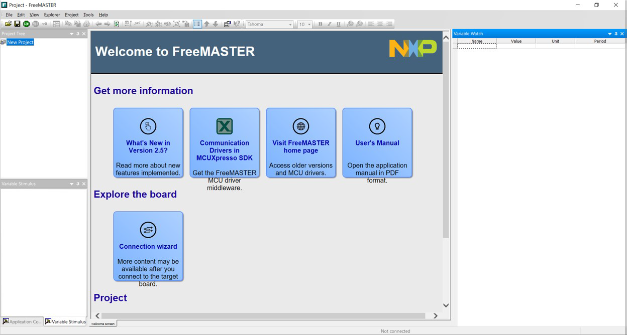
- Open the FreeMASTER application, the following welcome screen should be displayed
- Open the downloaded project from File System
- Open the NXP quad motor-control FreeMASTER project. Navigate to the File toolbar and select Open Project from the drop down menu.
- Browse in your local directory where the NXP quad motor-control FreeMASTER project is downloaded, select the pmsm_demo_QUAD_debug.pmp file and then click Open.
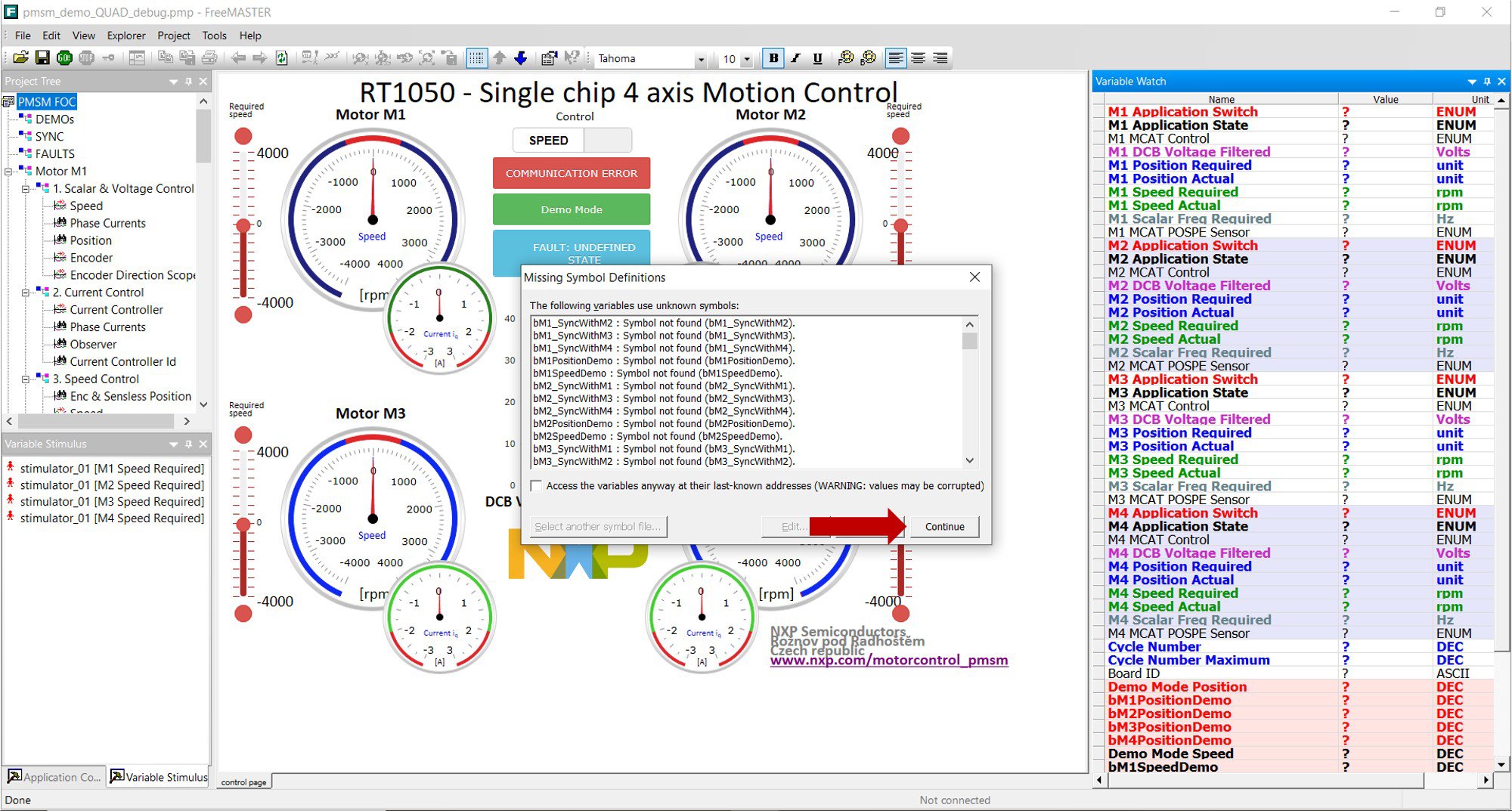
- A window warning there are symbol definitions missing might pop up, as there are variables that will not be initialized until the motors are running as shown in the next figure.
- For aditional information from the FreeMASTER project visit UM11340
Design Resources
Board Documents
Support
Trainings
このページ
- 2.1
MCUXpresso Integrated Development Environment (IDE)
- 2.2
MCUXpresso Project Sample Code
- 2.3
FreeMASTER Run-Time Debugging Tool
- 2.4
FreeMASTER Project Sample Code
- 3.1
Get the i.MX RT1050 SDK
- 3.2
Accept Terms and Download
- 3.3
Install the i.MX RT1050 SDK in MCUXpresso
- 3.4
Open the Quad Motor Control Project from File System
- 3.5
Building the Project